Base Frame Manufacturing

Chassis, Machine Frame & Baseframe Fabrication

Contents

Chassis & Base Frame Fabrication refers to the production of a structural framework or base component that serves as the foundation or support for a larger system, device, or equipment. These base frames are commonly used in various industries to provide structural integrity, ensure stability, and house components or machinery.

Machine Frame Painting

Materials for Base Frames

Carbon Steel Frames


  • Carbon steel is an alloy that can be easily fabricated (bent, rolled, and welded) into desired forms

  • It is the most economic and popular material for base frame and chassis applications

  • They can be coated with different types of coatings such as wet paint, powder coating or HDG.

Stainless Steel Frames


  • It’s an alloy of steel with chromium content that is a better resistant to rusting and corrosion
  • It offers great protection for corrosive chemicals, liquids and substances.

  • Its significantly higher cost compared to carbon steel and aluminium is the major drawback

Aluminium Frames


  • Aluminium offers a lightweight, corrosion-resistant, and durable solution

  • Aluminum naturally forms a protective oxide layer, making it resistant to corrosion in harsh environments.

  • Aluminum combines low weight with good strength, ensuring durability and performance
Baseframe Manufacturing

Applications of Base Frames

Applications of Base Frames
Industry Application Specific Use Benefits
Industrial Equipment Heavy Machinery Compressors, pumps, generators, and turbines Stability, vibration reduction
Cranes Distributes load and prevents tipping during crane operations Stability, safety
Power Generation Generators Provides a stable foundation for power generators Vibration reduction, secure mounting
Transformers Supports large transformers in power plants and substations Stability, vibration control
Manufacturing Workstations Supports tools, assembly lines, and machinery in manufacturing Stability, precise alignment
Assembly Racks Holds parts during assembly, ensuring secure positioning Flexibility, modular design
HVAC Systems Air Handling Units Stable platform for air handling systems and compressors Vibration control, stability
Agriculture Tractors & Harvesters Foundation for engines and operational systems of large agricultural machines Stability, rugged durability
Irrigation Systems Supports pumps and water distribution systems Durability, stable operation
Packaging & Shipping Shipping Frames Secures heavy or bulky items for safe transport Stability, protection during transit
Pallets & Crates Structural support for pallets and crates in logistics Safe stacking, transport efficiency
Base Frame Fabrication Welding
Machine Frame Painting

Fabrication Steps of Baseframes and Chassis

Cutting and Preparing Materials

  • Cutting: The raw materials are cut to the required dimensions. This can be done using various methods such as laser cutting, plasma cutting, water jet cutting, or saw cutting, depending on the material and complexity.

  • Bending and Shaping: For tubular or bent sections of the chassis, materials are bent or shaped using CNC Press Bending Machines.

sheet metal fabrication - plasma cutting
Welding Base frame

Welding

  • Tacking and Positioning: The cut and shaped components are placed into position. Small tacks (temporary welds) are made to hold parts in place before the final welding process.

  • Welding: This step involves permanently joining the components using various welding techniques such as MIG (Metal Inert Gas) welding, TIG (Tungsten Inert Gas) welding with Welding Robots.

Machining & Heat Treatment

  • Machining: If required, the welded frame goes through CNC machining process to generally in Double Column Machining Centers.

  • Heat Treatment: Is used to increase the mechanical properties of the chassis material It can improve strength, hardness, toughness, and wear resistance.

Machining base frame
Chassis Fabrication

Surface Treatment

  • Grinding and Cleaning: After welding, excess material around welds may be ground down, and the entire chassis is cleaned of debris.
  • Wet Painting : Liquid paint is applied to the chassis using spray guns
  • Powder Coating: Applying dry powder to the chassis using an electrostatic charge.
  • Hot Dip Galvanization: Dipping the chassis into molten zinc bath, which coats the entire surface with a layer of zinc for corrosion resistance

Frame Assembly

Tips for Base Frame Manufacturing

  • Use jigs or fixtures to hold parts in place during welding. This ensures alignment and reduces the risk of warping or deformation due to heat.
  • Control heat input during welding to avoid distortion or weakening of the material. This is especially important for large structures or materials with low heat tolerance.
  • For large base frames, incorporate diagonal braces or supports to prevent twisting or bending under load.
  • Use measuring tools like laser scanners, calipers, or gauges to ensure all parts fit together correctly and dimensions are within tolerances.
  • If required, conduct load testing to verify the frame can withstand the required weight or forces without deformation.
  • Assemble the frame in stages, starting with the major components (e.g., base plate, vertical supports), ensuring everything aligns before fully tightening or welding.
  • Large CNC milling machines or horizontal boring mills are typically used for the machining of base frames.
Base Frame Manufacturing

Dimensional Drift in Welded Base frames
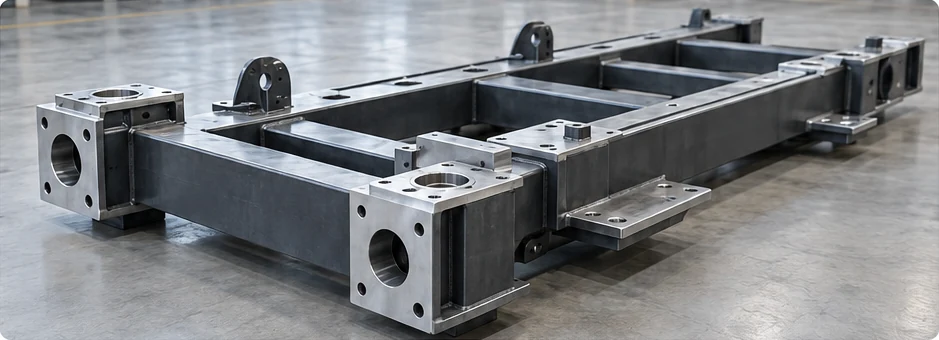
Generated steel baseframe with precision-machined mounting pads.

Background

During a fabrication project at Novelty Structures, an initial manufacturing sequence resulted in unexpected dimensional movement after final machining. The original plan was to complete welding, send the baseframe for thermal stress relief, and then execute all machining operations. However, removing significant amounts of metal during final machining reintroduced secondary stresses and altered the final tolerances.

The Solution & Sequence Optimization

Novelty Structures revised the manufacturing route to split machining into two distinct stages, placing thermal stress relief between rough cutting and final finishing:

Original Sequence

Welding

Thermal Stress Relief

Final Machining

Revised Best-Practice Sequence:

Welding

Rough Machining

Thermal Stress Relief

Final Machining

By rough machining first, the bulk of material removal and its associated stresses took place before heat treatment. Thermal stress relief then stabilised both the weldment and the rough-machined surfaces, leaving only light finishing cuts to achieve the exact final geometry. This process aligns with established heat-treatment guidance, which recommends stress relieving after rough machining to minimise post-finishing movement.

Novelty Structures’ Best Practices for Precision Machining

  • Leave Sufficient Finishing Allowance: Ensure rough machining retains enough stock material to reach exact dimensions following heat treatment.
  • In-Process Dimensional Audits: Measure and log frame dimensions immediately after rough machining and again post-stress relief before starting finishing cuts.
  • Standardise Inspection Conditions: Establish fixed inspection protocols, including agreed support locations, measurement references, and stable ambient temperatures.
  • Select Purpose-Fit Heat Treatment: Match stress-relief cycles directly to the specific material grade, frame geometry, and functional requirements.

Case Study : Oversized Machine Chassis
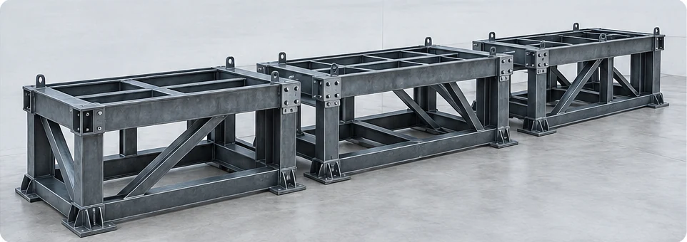
Generated modular steel machine support frame with bolted assembly joints.

Background

When designing large-scale structural frames—such as an 18-metre long, 4-metre wide machine support cradle—a single-piece frame creates severe manufacturing, coating, and transport bottlenecks. While structurally sound on paper, single-piece frames often exceed road transport limits, galvanising bath sizes, and machine shop capacities.

The Solution & Process Optimisation

Novelty Structures addresses large frame design by dividing the structure into manageable, transportable modules with structural bolted splice joints. To overcome potential alignment challenges during site installation, trial assemblies are performed in the workshop before dispatch.
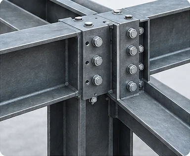
Generated close-up of a bolted steel frame splice.

Production Route Checklist

Before finalising module dimensions and connection details, Novelty Structures evaluates the design against every stage of the manufacturing journey:

Production Stage Engineering Design Considerations
Fabrication & Handling Module weight, centre of gravity, lifting lug locations, and turning clearance during welding.
Machining Machine bed envelope, table load limits, tool access, and clamping clearance—not just nominal frame size.
Galvanising Kettle dimensions, dipping orientation, suspension points, and internal venting/drainage.
Surface Coating Access for grit blasting, paint spray clearance, and curing oven dimensions.
Transport & Delivery Transport envelope, route height/width restrictions, crane offloading limits, and site access.
Final Assembly Joint access, reference datums, bolt torque access, and final alignment verification.

Best Practices for Modular Structures

  • Align Finishing with Joint Details: In line with industry galvanising capacity, coordinate oversized or double-dipped items early and execute bolted joint connections after galvanising.
  • Balance Module Count Against Assembly Effort: Smaller modules increase options for machining and coating facilities, but each joint adds connection detail and assembly labour.
  • Define Joint Machining Strategy: Establish early whether modules can be machined independently and aligned during assembly, or if critical mating surfaces require secondary machining in an assembled state.

Case Study 2: Cost Optimisation in Frame Design

Background

On complex chassis projects, applying tight tolerances uniformly across an entire fabrication significantly drives up manufacturing costs. In many cases, a complete multi-ton frame must be secured on an ultra-large CNC machining centre simply to finish a few small mounting pads.

The Solution & Process Optimization

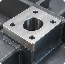
Novelty Structures isolates critical functional interfaces from surrounding structural components. By concentrating precision machining strictly on defined mounting surfaces, the overall frame remains in a standard fabricated condition without compromising machinery performance.
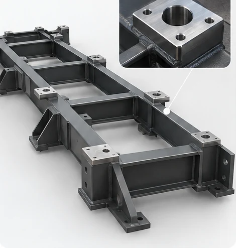
Generated baseframe with raised machined mounting pads and a locating bore detail.

Tolerance Allocation Review Framework

Frame Feature Evaluation Metric Strategic Design Action
Equipment Mounting Pads Which surfaces require controlled flatness, height, or alignment? Machine raised pads only, keeping surrounding frame unmachined.
Locating Bores & Holes Which holes position equipment vs. providing clearance? Precision-bore critical alignment points; use clearance holes for fasteners.
Outer Frame Boundaries What variance can surrounding installation space accept? Apply standard structural steel fabrication tolerances.
Non-Contact Surfaces Is machining functionally necessary for operation? Retain approved as-welded or coated finish without post-weld cutting.

Best Practices for Cost-Effective Design

  • Pre-Release Drawing Reviews: Consult fabricators and machining suppliers prior to finalizing drawings to confirm tolerances can be met with practical setups (a principle supported by established machining design guidance).
  • Design Isolated Tool Access: Incorporate raised mounting pads that allow tool access without requiring machining over large structural areas.
  • Require Designer Sign-Off: Ensure any tolerance relaxation is formally approved against functional performance requirements.
Generated close-up of a machined mounting pad and locating bore.

Case Study 3: Planning for Hot-Dip Galvanised Hollow Base frames

Background

A fully welded hollow-section baseframe met all structural and dimensional requirements but required unexpected shop-floor modifications before hot-dip galvanising. Sealed tubular members, capped ends, and internal partition plates lacked proper venting and drainage openings.

The Solution & Process Optimisation

During hot-dip galvanising at ~450°C, trapped air inside closed sections expands rapidly, posing safety risks, while trapped cleaning acids prevent zinc coverage. Novelty Structures incorporates internal venting and drainage detailing directly into the 3D model stage in accordance with industry galvanising design guidelines.
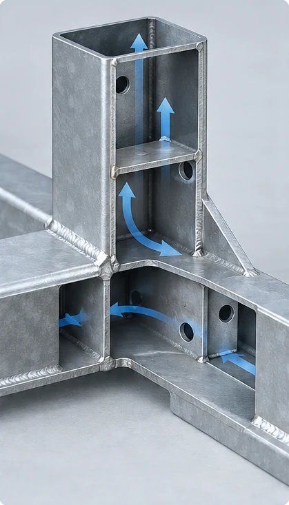
Conceptual hollow-section cutaway illustrating venting and drainage; not a production detail.

Hollow-section venting and drainage

Galvanising Review Checklist

  • Capped Tubes & Partitions: Identify every internal chamber and place vent/drain holes at diagonal extremes.
  • Intersecting Hollow Sections: Ensure internal connection points allow free passage of air and molten zinc between joined members.
  • Gussets & Pockets: Crop internal stiffener corners and open pockets where zinc or air could become trapped based on dipping orientation.
  • Thermal Distortion Control: Evaluate differences in section thickness and asymmetric geometry to prevent warping from high galvanising bath temperatures.

Novelty Structures’ Best Practices for Galvanised Baseframes

  • Pre-Manufacture Galvaniser Review: Confirm dipping angles, handling arrangements, and venting layouts with the galvaniser before approving production drawings.
  • Coordinate Finishing and Tolerance Audits: Agree on when critical dimensions are verified relative to the galvanising process, and plan post-galvanising thread clearing or pad machining accordingly.

How can we help you ?

Chassis and baseframe fabrication services are indispensable to various industries and their success depends on the careful selection of fabrication suppliers.

Novelty Structures stands out as a reliable partner in providing high-quality machine frame and baseframe fabrication services tailored to demanding industrial needs.

Contact our team to further discuss your needs.

Knowledge Hub