

Novelty Structures provide custom CNC machining services for components and industrial applications from our facilities in Turkey
Contents
- Machining Operations
- Materials
- Quality Control
- Design for Machining
- CNC Machining Cost Drivers
- Why Choose Us?
- Challenges in CNC Machining
- Coatings for Machined Parts
- Case Study 1: Tight Tolerances Might Be Burning Your Budget
- Case Study 2: Alignment Errors in Valve Machining
- Case Study 3: Shop Floor Temperatures to ruin Quality Control
- How can we help you ?
- FAQ
Machining is a manufacturing process that creates the desired form by removing small chips of material from the work piece. CNC machining uses computer-controlled tools to produce machined components, increasing efficiency and reducing costs through automation.

Machining Operations


Materials
Metals

Plastics

Quality Control

CNC Machining Cost Drivers

Challenges in CNC Machining
Coatings for Machined Parts
Choosing the right surface finish for machinery components is a balancing act between environmental protection, wear resistance, and tight dimensional fit. A carbon-steel shaft, an aluminum housing, and a stainless-steel fitting handle corrosion totally differently. Even on one part, a bearing journal needs micron-level dimensional accuracy while an exposed body needs tough rust protection. Working as technical advisors for a Novelty Structures' client, our team put together a straightforward framework for matching coatings to part function.
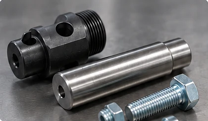
Steel surface finishes
Surface Treatment Types
To avoid common headaches like stuck threads, stripped fits, or premature rusting, treatments must be chosen by function and planned with exact pre-machining allowances. Here is the practical guide covering six main component categories:
1- Corrosion Protection for Carbon Steel
| Treatment Option | Best Used For | Key Process & Tolerance Controls |
|---|---|---|
| Zinc electroplating | Small steel components, pins, fasteners, and fittings. | Check coating thickness, clear passivates/topcoats, and allow for thread fit tolerances. |
| Zinc–nickel plating | Severe service environments needing higher protection than basic zinc. | Specify 12-15% Ni alloy blend, total layer thickness, and dimensional fit allowances. |
| Zinc–iron plating | Alternative zinc-alloy sacrificial coating option. | Establish performance requirements, passivate choice, and topcoat compatibility. |
| Zinc-flake coating | Fasteners, clips, and high-strength steel hardware. | Non-electrolytic dip-spin application; confirm thread clearances and friction coefficient. |
| Hot-dip galvanising | Heavy-duty exposed steel fabrications and outdoor structural hardware. | Plan for thick coating build-up, thread re-tapping, moving part clearances, and heat warping risks. |
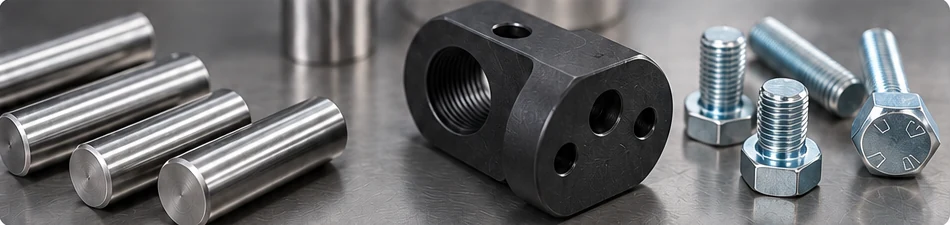
2- Conversion Treatments & Temporary Protection
| Treatment Option | Best Used For | Important Limitations & Notes |
|---|---|---|
| Black oxide + oil/sealer | Dark aesthetic finish, lubricity, and low dimensional change. | Corrosion resistance depends on oil layer; not suitable for prolonged outdoor exposure. |
| Zinc phosphating | Pre-paint priming base or oil-absorbing rust protection. | Must be paired with compatible paint, oil, or sealer to work properly. |
| Manganese phosphating | Oil retention and wear reduction during break-in of moving parts. | Check surface texture, mating clearances, and operating oil lubrication. |
| Rust-preventive oil/wax | Short-term protection during storage, shipping, and handling. | Set clear protection duration, storage conditions, and cleanup steps before final assembly. |
3- Paints and Organic Coatings
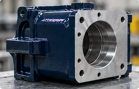
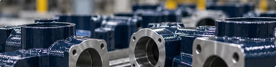
Masked housing face
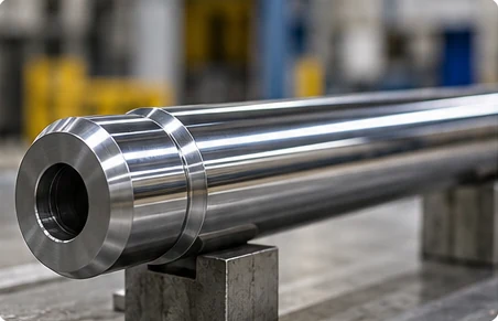
Polished hydraulic rod
| Treatment Option | Suitable Substrates | Main Selection Advantages |
|---|---|---|
| Epoxy primer / system | Prepared carbon steel and pretreated metals. | Outstanding barrier protection and chemical resistance in harsh environments. |
| Polyurethane topcoat | Steel and aluminum over compatible primers. | Great outdoor weatherability, color stability, UV protection, and gloss retention. |
| Zinc-rich primer | Grit-blasted structural steel. | Provides sacrificial galvanic protection under tough industrial paint systems. |
| Powder coating | Steel and aluminum sheet metal or structural parts. | Durable, high-impact decorative finish; requires clear masking on precision fits. |
| Electrocoating (E-coat) | Conductive metal parts with chemical pretreatment. | Uniform, highly controlled coverage on complex geometries and high-volume runs. |
4- Wear and Friction Coatings
| Treatment Option | Substrate Materials | Main Purpose & Machining Tips |
|---|---|---|
| Electroless nickel plating | Steel, stainless steel, and aluminum. | Deposits completely even thickness across complex shapes; excellent wear and corrosion resistance. |
| Electrolytic nickel plating | Steel and conductive metals. | Protective functional layer; watch out for extra thickness build-up on sharp edges. |
| Hard chromium plating | Steel shafts, hydraulic rods, and wear faces. | Extremely hard, low-friction surface; budget for post-plating grinding or polishing. |
| Dry-film lubricant | Steel, stainless steel, and aluminum. | Reduces friction and galling; specify load capacity, temperature rating, and thickness. |
| Thermal-spray coating | Steel and metallic substrates. | Heavy wear restoration or hardfacing; requires final grinding to achieve finished dimensions. |
5- Aluminium & Stainless Steel Finishing
| Treatment Option | Target Material | Key Operational Considerations |
|---|---|---|
| Conventional anodising | Aluminium alloys | Corrosion protection and color; account for 50% growth / 50% surface penetration on fits. |
| Hard anodising | Aluminium alloys | Maximum wear resistance and surface hardness; set exact pre-plating machining dimensions. |
| Chemical conversion coating | Aluminium alloys | Corrosion protection and paint prep while keeping surface electrical conductivity. |
| Passivation | Stainless steel | Removes free iron contaminants to restore natural oxide layer; zero dimensional change. |
| Electropolishing | Stainless steel | Improves micro-finish and cleanability via controlled electrochemical smoothing. |
6- Surface Hardening Processes
| Treatment Option | Best Used For | Drawing Callout Essentials |
|---|---|---|
| Nitriding | Hard, wear-resistant surface on alloy steels with minimal heat warping. | Specify steel grade, target surface hardness, case depth, and masked areas. |
| Ferritic nitrocarburising | Improved wear, scuffing, and fatigue resistance on carbon/alloy steels. | Define layer properties, dimensional growth limits, and post-oxidation options. |
| Carburising and hardening | High surface hardness combined with a tough, shock-resistant core. | Specify case steel, target depth, hardness, and post-heat grind allowances. |
| Induction hardening | Selective localized hardening of specific wear areas (e.g., gear teeth, shaft journals). | Define hardened zones, transition boundaries, hardness levels, and minimum depth. |
Practical Engineering Tip: Pre-Plating vs. Post-Plating Dimensions
Always state clearly on the drawing whether tolerances apply before or after surface treatment. For instance, a steel locator pin needed corrosion protection on its exposed ends while keeping a tight slide fit on its middle section. Plating the entire pin made the middle section too thick to fit. The team fixed this by masking the middle section during electroplating and applying a light rust-inhibitor oil after machining.
Also, for high-strength steel parts (tensile strength ≥ 1000 MPa) getting electroplated or acid-cleaned, don't forget mandatory hydrogen embrittlement baking (190°C–220°C for 4–24 hours) right after plating to prevent sudden brittle cracking.
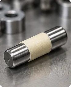
Masked locator pin
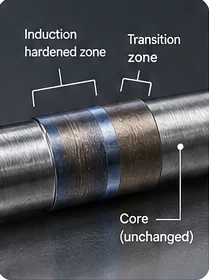
Shaft hardening zones
Case Study 1: Tight Tolerances Might Be Burning Your Budget
When a long-time engineering partner reached out to Novelty Structures to review a carbon-steel drive shaft for a conveyor system, they were facing a familiar headache: rising production costs and long machine cycle times. Super tight tolerances look great on paper, but every extra decimal place forces a workshop to use specialized grinding, electrical discharge machining (EDM), or extra finishing passes. When those tight numbers support bearing fits or dynamic seals, they're 100% worth it. But when applied everywhere by default, you're paying for precision that adds zero value to the product.
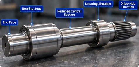
Stepped drive shaft
The part in question was a stepped drive shaft designed for continuous conveyor duty. Looking at the blueprint, five main features stood out:
The original drawing applied a blanket tight tolerance (±0.005 mm) and a ultra-fine surface finish (Ra 0.4 µm) across every single one of these sections. Before locking in the production plan, our team sat down to do a Design for Manufacturability (DFM) review to see what each callout was actually doing.
Design for Manufacturing (Dfm) Review
We evaluated each feature against its real job in the assembly:
| Shaft Feature | What the Review Established | Practical Machining Impact |
|---|---|---|
| Bearing seats | Needs precise fit, smooth finish, and alignment between seats. | Keep tight turning and fine grinding to guarantee smooth bearing operation and fatigue life. |
| Drive-hub location | Needs proper fit to transfer drive torque without slipping or slop. | Keep exact dimensions and keyway features intact for solid power delivery. |
| Locating shoulders | Positions bearings or hubs axially along the shaft. | Keep strict control over shoulder faces to prevent bearing misalignments. |
| Reduced central section | Clears internal housing; doesn't contact mating parts or dynamic seals. | Relax the tolerance! A standard turned finish works fine here while keeping strength intact. |
| End faces & overall length | Determines overall fit within open machine space. | Separate loose clearance needs from tight fits, easing length tolerances significantly. |
The biggest breakthrough came from the reduced section in the middle. Since it doesn't touch anything or house seals, forcing a micro-smooth ground finish was just wasting machine time. However, we made sure to keep its minimum diameter safe for torsional strength and kept smooth transition radii so fatigue strength stayed solid.
The Result: Smarter Machining, Lower Cost
We flagged the over-engineered call-outs, showed the customer’s engineering team the unnecessary steps, and got approval for a revised drawing. Leaving the central section at a standard turned finish while saving precision grinding strictly for the bearing seats cut machining time down fast. Connecting the updated drawing straight to the CNC programming and quality check sheet made sure production ran smoothly without any confusion.
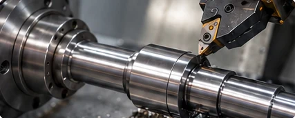
Shaft turning detail
Case Study 2: Alignment Errors in Valve Machining
When machining heavy industrial valves, hitting the right bore diameter isn't enough. If the bore axis is tilted even half a degree, the valve stem will bind. If flange bolt holes are slightly off-perpendicular, the valve won't seal tightly against the pipeline. A factory working as a Novelty Structures' client hit this exact wall during multi-stage valve body machining, suffering high scrap rates and costly manual rework.
What Was Going Wrong?
The workshop was machining medium and large valve bodies in two separate setup steps on horizontal boring mills. Between steps, operators had to manually index and re-clamp the heavy castings. Minor setup errors quickly stacked up:
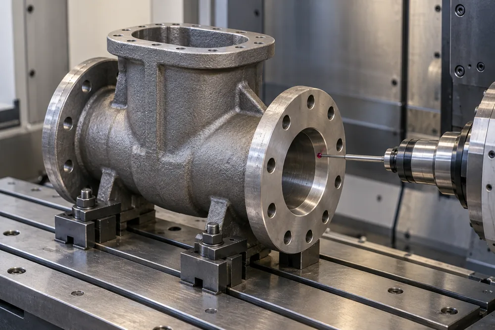
Valve body probing
Because traditional quality control checked parts only after machining was finished, setup mistakes meant throwing away fully machined components. That meant lost spindle hours and wasted material.
The Fix: Automated In-Machine Probing
Instead of relying on manual indicator setups and hoping for the best, the engineering team introduced automated on-machine probing. Right after re-clamping the part, an touch probe automatically checks the casting's position and orientation, updating the CNC machine's Work Coordinate System (WCS) live before the cutter touches the metal.
To keep drawing reviews organised across all housing and valve projects, the team created a handy Critical Feature Checklist:
| Key Drawing Review Question | Why It Matters on the Shop Floor |
|---|---|
| Which features drive fit, motion, sealing, or alignment? | Gives a clear functional reason for tighter geometric callouts like perpendicularity or runout. |
| What exact form or position requirement applies? | Specifies what the operator or probe needs to measure (e.g., bore alignment, face squareness). |
| Which datum references set the baseline? | Shows how the part must be located and clamped during both machining and quality checks. |
| Does re-clamping the part affect these relationships? | Flags multi-setup steps where automated probing checks are essential before cutting. |
| Does acceptance happen before or after heat treat / coating? | Ensures dimensional allowances are planned correctly before final inspection. |
The Results: Zero Scrap and Faster Setups
Linking clear critical feature IDs on drawings directly to inspection sheets transformed shop floor operations:
Case Study 3: Shop Floor Temperatures to ruin Quality Control
Have you ever had a part fail inspection in the afternoon even though the exact same CNC program was running fine all morning? Before tweaking machine offsets or blaming the operator, check the shop floor thermometer! During a high-volume engine component project for a Novelty Structures client, ambient shop temperature shifts were throwing measurement readings off and creating false quality alarms.
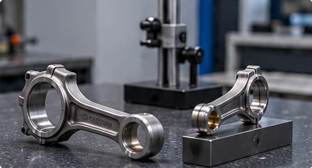
Connecting rod gauging
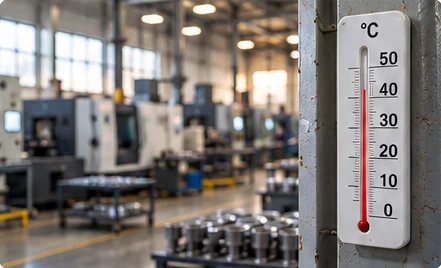
Workshop thermometer
2. The Math Behind Shop Floor Temperature Shifts
We produced engine connecting rods for heavy-duty compressors, tractors, and commercial vehicles. In summer, shop floor temperatures swung from 19°C during early morning shifts up to 40°C by mid-afternoon. Standard quality call-outs reference dimensions at 20°C .
When temperature rises, both the steel part and the measuring tool expand. Thermal expansion follows a simple formula:
Where L = 200 mm baseline length, α = 11.5 × 10⁻⁶ / °C for steel, and ΔT = temperature difference from 20°C standard.
Here is what that math looks like in real life:
Since connecting rod bore tolerances are as tight as 10–15 µm, an uncompensated thermal expansion of 46 µm made warm parts look way oversize. Operators kept adjusting CNC offset parameters, which accidentally ruined cold-part dimensions once parts cooled back down overnight!
The Fix: Comparative Gauging & Master Artifacts
Installing a multi-million-dollar air conditioning system in a heavy machine hall wasn't realistic. Instead, the plant set up a Shop-Floor Comparative Gauging Routine:
Shop Floor Metrology Routine
To keep quality stable across all shifts, the factory adopted this 6-step shop floor inspection routine:
| Routine Step | What to Do on the Shop Floor |
|---|---|
| 1. Identify temperature-sensitive checks | Flag tight tolerance features where thermal expansion is big relative to the tolerance band. |
| 2. Set measurement conditions | Record part temperature directly. Ambient air temp alone doesn't reflect a freshly machined part. |
| 3. Allow part stabilization time | Let parts coming off warm machining or washing lines equalize before taking final readings. |
| 4. Verify gauge & master condition | Clean locating surfaces and check reference master condition following validated procedures. |
| 5. Investigate before changing CNC offsets | Re-check master reference before tweaking code. Never adjust offsets based on one warm reading! |
| 6. Save audit trail evidence | Log measurement numbers, ambient conditions, and calibration times for quality records. |
The Results: Fast Cycles, Zero False Scrap
Using comparative mastering brought total stability to shop floor quality control:
How can we help you ?
CNC machining services are indispensable to various industries and successful projects depend on carefully selecting machining contractors.
Novelty Structures stands out as a reliable partner in providing high-quality CNC machining services tailored to demanding industrial needs.
FAQ
Contract CNC machining refers to outsourcing precision manufacturing tasks to a specialized provider. These services involve computer-controlled machining processes to produce high-quality parts or components from various materials, including metals, plastics, and composites.
Our facility utilizes a wide range of CNC machines, including:
- CNC mills
- CNC lathes
- 5-axis machining centers
- Swiss-style lathes
- CNC routers
Lead times depend on project complexity, material availability, and order volume. Prototyping projects often take 1-3 weeks, while production runs may take 4-8 weeks. Expedited services are available for urgent needs.
Yes, we offer a variety of finishing services, including:
- Anodizing
- Powder coating
- Polishing
- Sandblasting
- Heat treatments
- Plating (e.g., chrome, nickel)
Yes, we have CNC machines capable of handling large parts and assemblies. Our facilities include machines with extended work envelopes and multi-axis capabilities to accommodate oversized or complex components.
Yes. We can machine custom threads (both internal and external) and create specialized features such as undercuts, thin walls, deep pockets, and complex contours based on your specifications.
We ship globally using a variety of carriers. Depending on your location and urgency, we can provide standard shipping, expedited shipping, or freight options for large orders.
Yes, we can combine CNC machining with other processes such as injection molding, die casting, 3D printing, and metal stamping for a complete manufacturing solution.
Yes, our precision CNC machines are equipped to produce small, intricate components with features like micro-holes, fine threads, and detailed engravings.
Yes, to ensure manufacturability, consider the following:
- Avoid overly thin walls or deep pockets.
- Specify radii for inside corners.
- Use standard hole sizes where possible.
- Minimize excessive tolerances unless necessary.
If defective parts are identified, we will replace them free of charge. We work closely with our clients to address any issues promptly and improve future production runs.
Yes, we provide post-production assembly services, including mechanical assembly, fastening, and packaging, depending on your project’s needs.


Stainless Steel CNC Machining Service for Custom Part Manufacturing Stainless [...]

Novelty Structures offers Contract Gear Manufacturing of Helical Gears, Spur Gears, Bevel Gears, Gear [...]

Shaft manufacturing requires various operations from forging to machining, tailored for diverse mechanical roles [...]

Contract CNC Turning Services and Custom Turned Parts Manufacturing CNC Turning [...]
Gallery


