

Sheet Metal Fabrication Services for Carbon, Galvanised, Stainless Steel and Aluminium
- Laser Cutting
- Plasma Cutting
- Water Jet Cutting
- CNC Punching
- Press Brake Bending
- Deep Drawing
- Tig Welding
- Mig Welding
- Spot Welding
- The Challenge:
- Our Approach & Solution:
- Key Results & Best Practices
- Total Operations Focus:
- Engineering Validation:
- LESSON LEARNED:
- The Challenge:
- Our Approach & Solution:
- Fabricator Review Protocol
- Bend Zone Proximity:
- Multi-Bend Span:
- Reference Datum Alignment:
- Non-Critical Flexibility:
- LESSON LEARNED:
- The Challenge:
- Our Approach & Solution:
- The Challenge:
- Our Approach & Solution:
- Standardized Execution Workflow
- First-Bend Qualification:
- Unloaded Geometry Check:
- Full Part Verification:
- Process Parameter Logging:
- LESSON LEARNED:
- The Challenge:
- Our Approach & Solution:
- Key Performance Outcomes
- Single-Pass Capacity:
- Deposition Output:
- Gap Tolerance Validation:
- LESSON LEARNED:
- The Challenge:
- Our Approach & Solution:
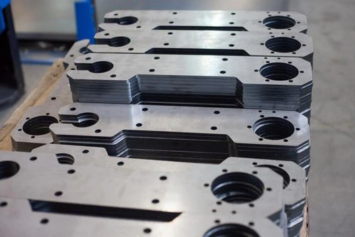
Sheet Metal Fabrication Steps
Cutting


Forming

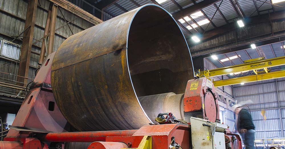


Materials used in Sheet Metal Fabrication

Challenges
Sheet metal fabrication offers many benefits, but it also presents a range of challenges. Here are some of the key challenges in sheet metal fabrication:

How can we help you ?
Novelty Steel has a proven track record of delivering sheet metal components to meet client requirements.
Our deep understanding of mild steel, aluminium and stainless steel and their unique forming characteristics enables us to meet the required quality criteria.
We offer sheet metal fabrication services tailored to each project, from sample fabrications to mass production.
Knowledge Hub
Sheet Metal Fabrication & Manufacturing Case Studies
Practical Engineering Insights: Design for Manufacturability, Quality Control & Assembly Optimization
EXECUTIVE SUMMARY: This case study document summarizes real-world engineering projects focused on optimizing sheet metal fabrication, controlling fit tolerances, managing coating thicknesses, adapting to high-strength steel grades, and standardizing robotic welding sequences.
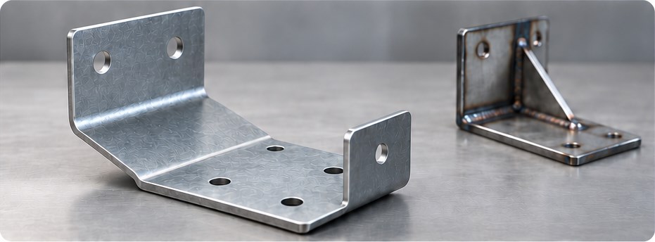
Folded support bracket
Case Study 1: Re-Engineering a Support Bracket for One-Piece Bending
The Challenge:
We inherited a support bracket design originally created for a legacy manufacturing method. The original assembly comprised three separate component parts joined by four distinct weld seams, with internal threads requiring separate tapping operations.
Our Approach & Solution:
We evaluated whether the separate welded pieces were strictly necessary or if the joints could be replaced with press brake bends. By redesigning the bracket into a single bent component, we completely eliminated all four weld seams. Incorporating an additional strategic bend increased structural rigidity, enabling us to safely transition to a thinner sheet metal gauge.
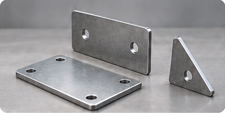
Support bracket components
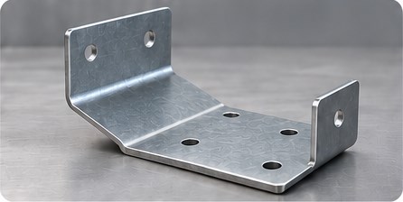
Redesigned one-piece bent bracket
Key Results & Best Practices
Total Operations Focus:
Shifted our evaluation metric from the unit cost of individual operations to reducing the overall count of manufacturing steps, positioning labor, and seam finishing.
Engineering Validation:
Each proposed assembly simplification was systematically re-validated against operational loads, stiffness targets, mounting interfaces, and press brake bending clearance.
Case Study 2: Managing Hole Distortion and Multi-Bend Tolerances
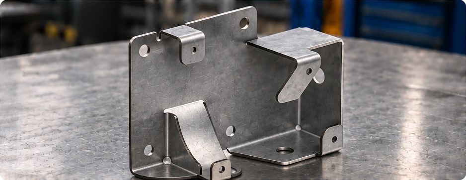
Formed mounting interfaces
The Challenge:
Custom sheet metal components intended to attach to an existing chassis were experiencing fit-up issues during final integration. Although holes were accurately placed in the flat 2D cutting pattern, material deformation near bend zones caused hole distortion, while tolerance accumulation across multiple bends compromised mounting precision.
Our Approach & Solution:
We shifted our quality focus from flat-pattern dimensions to specifying the required geometric relationships in the fully formed 3D condition. Before releasing final fabrication drawings, we established a structured design review protocol with our fabricators.
Fabricator Review Protocol

Bend Zone Proximity:
Identified all holes and slots located close to active deformation zones.

Multi-Bend Span:
Analyzed critical mounting dimensions that spanned across several consecutive bends.

Reference Datum Alignment:
Agreed on the primary reference faces and edges used to locate fit-critical features.

Non-Critical Flexibility:
Highlighted non-functional features where positional variation could be safely relaxed.
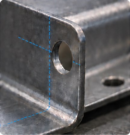
Formed mounting interfaces

Case Study 3: Surface Coating Thickness and Functional Surface Clearances
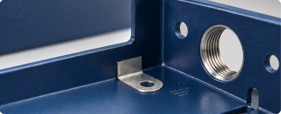
Coating and contact surfaces
The Challenge:
Sheet metal parts that passed dry-fit inspections prior to surface treatment frequently bound or failed fit checks after final finishing. Applied paint and powder coatings added unexpected material layer thickness, altering thread tolerances, tightening close-clearance openings, and blocking required electrical grounding paths.
Our Approach & Solution:
We integrated coating requirements directly into the upfront component drawings rather than treating surface finishing as an isolated post-process.
| Functional Feature Area | Engineering Specification & Protection Requirement |
|---|---|
| Threaded Holes & Inserts | Specified protective masking or post-tap requirements to prevent thread binding. |
| Mating Surfaces | Identified tight-clearance interfaces where coating thickness directly affects assembly tolerance. |
| Electrical Grounding Points | Defined explicit un-coated contact zones for electrical continuity alongside appropriate corrosion protection. |
| Cosmetic Exterior Faces | Designated key visible surfaces requiring specific cosmetic appearance standards. |
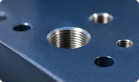
Threaded hole detail
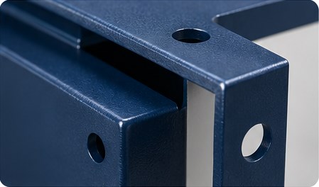
Mating surface detail
Case Study 4: Material Grade Transition and Press Brake Springback Control
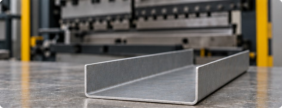
Press brake formed heavy steel channel
The Challenge:
When upgrading side-dump trailer fabrications from standard mild steel to high-strength structural steel, our production team encountered severe press tonnage spikes and unpredictable springback, causing formed parts to mismatch adjoining welded sub-assemblies.
Our Approach & Solution:
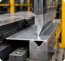
We deployed material-specific calculation models to estimate required bending forces, anticipate springback angles, and configure appropriate press brake tooling setups.
Standardized Execution Workflow
1
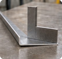
First-Bend Qualification:
Treated the initial bend as a mandatory process-validation check whenever steel grade, thickness, or tooling was changed.
2
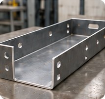
Unloaded Geometry Check:
Measured the unloaded bend angle and critical fit dimensions prior to approving the full production run.
3
Full Part Verification:
Inspected the overall geometry of completed multi-bend parts rather than evaluating individual angles in isolation.

4
Process Parameter Logging:
Recorded approved material batches, tooling IDs, and press settings together for future repeatability.
Case Study 5: High-Deposition Robotic Welding for Heavy Equipment Frames
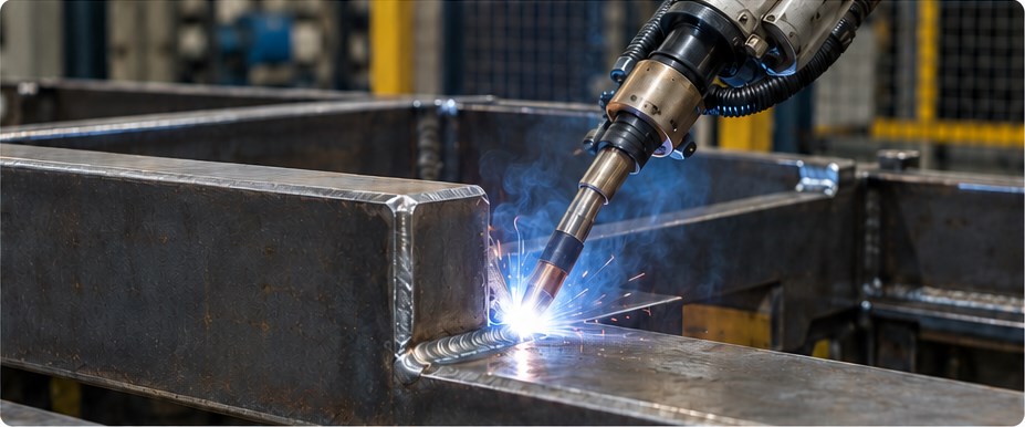
Robotic frame welding
The Challenge:
Heavy earth-moving equipment frames constructed from 10 mm mild steel plate required continuous fillet welds with a minimum throat thickness of 6 mm. Multi-pass manual welding was creating a severe production bottleneck.
Our Approach & Solution:
We implemented a robotic welding cell utilizing a matched filler wire and a pulsed arc welding process to maximize deposition without compromising joint integrity.
Key Performance Outcomes
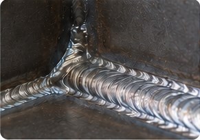
Single-Pass Capacity:
Produced a ~7 mm fillet weld throat in a single pass with complete root penetration and zero undercut.
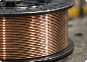
Deposition Output:
Achieved a steady deposition rate of 8 kg/h.
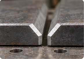
Gap Tolerance Validation:
Validated parameter stability on test joints incorporating realistic fit-up gap variations rather than perfectly fitted ideal samples.
Case Study 6: Dimensional Control and Distortion Management in Carbon Steel Weldments
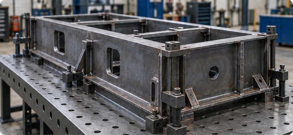
Weldment dimensional inspection
The Challenge:
Complex carbon steel fabrications that aligned in welding fixtures shifted out of tolerance during welding or sprang out of alignment the moment clamping fixtures were released.
Our Approach & Solution:
We implemented a standardized joining sequence that controlled tack-weld sizing, spacing, and sequencing to manage thermal movement across the assembly.
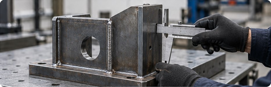
Weldment dimensional inspection
| Checkpoint Stage | Control Objective & Verification Action |
|---|---|
| Checkpoint 1: Post Fit-Up & Tacking | Confirm joint gaps, primary reference dimensions, and structural alignment remain within specified limits prior to main welding. |
| Checkpoint 2: In-Process Welding | Monitor thermal movement during the welding sequence to detect and correct distortion before later passes lock in stress. |
| Checkpoint 3: Post-Cooling & Fixture Release | Verify that the un-clamped, fully cooled assembly meets final acceptance dimensions without relying on fixture force to hold shape. |

