

Novelty Structures is a metal fabrication supplier in Turkey with experience in Carbon Steel, Stainless Steel and Aluminium components.
Metal fabrication is the process of cutting, shaping, and assembling metal materials—such as steel, stainless steel, aluminum, or alloys—into finished products or components.
It involves techniques like cutting, welding, machining, bending, and finishing, tailored to meet specific design and functional requirements.

Materials & Grades
Carbon Steel
Characteristics:
Fabrication:
Grades:
Stainless Steel
Characteristics:
Fabrication:
Grades:
Aluminium
Characteristics:
Fabrication:
Grades:

Operations
Cutting
Laser cutting is a thermal cutting process that uses a computer-directed high-powered laser together with an active gain mechanism (either gas or optical fiber) to concentrate the laser.
Fiber laser cutting is typically the premier choice for metal fabrication applications. Although laser cutting was developed in 1960s, industrial laser cutting become the metal fabrication norm in the late 1990s by professional metal fabricators.
There are currently two methods of laser cutting machines — CO2 laser cutters and fiber laser cutters. Both use a laser to create a beam used to cut metal, but fiber laser us optical fiber to concentrate the beam whereas the CO2 lasers use gas. Each type of laser does have its strengths and distinct use cases, CO2 is an older technology and fiber lasers are gaining market fast as the technology advances. With the speed benefits, almost half of the operating costs and three to four times greater throughput than CO2 lasers, fiber lasers offer greater opportunities in terms of financial gain. Check our article about Fiber vs Co2 Laser Cutting
Laser Cutting provides designers with the ability to let their imagination run wild without worrying about the upfront costs of custom punch and stamp tools.
Laser Cutting is a cost effective metal cutting process that can be used in rapid prototyping through to mass production of mild Steel, stainless steel, aluminium, copper and brass.
Plasma Cutting is a sheet metal cutting technique which can cut through any conductive metal. This includes metals like steel, aluminium, brass, titanium and copper – either thick or thin.
Plasma cutting works by passing a hot plasma through conductive metals to cut through it. To make the plasma, an electric arc is passed through a gas such as nitrogen or oxygen. This creates a fourth state of matter called plasma. The plasma can then be forced through a small opening like a nozzle, which can then cut through conductive metal.
Plasma Cutter cut performance is quoted for mild steel. Stainless Steel and Aluminium require more power, so generally, cut performance will be less for these materials.
Although plasma cutting offers low investment and operating costs, the cutting quality is not as precise as laser cutting machines. Therefore plasma cutting is a more preferable means of cutting for thick sheet metals and high tolerance applications.
Check our article about Laser cutting vs Plasma cutting.
Shearing is a metal fabrication process that’s used to trim and remove unwanted material from sheet metal. It involves the use of a machine or tool, such as a bench shear, to slice through sheet metal with extreme precision. Shearing doesn’t require the use of heat — sheet metal is typically sheared while cold or at room temperature — nor does it produce waste in the form of chips, making it an attractive choice for manufacturers.
Shearing is a fast cutting method, performed in seconds and offers smooth edges. It is cost-effective for high-volume manufacturing applications. However, the shear length is limited to the capacity of the shear machine. Also shearing does not allow non-linear cutting.
Sheet metal punching is a cutting process in which material is removed from a piece of sheet metal by applying a shearing force. CNC Punching can be used to produce holes and special cut-outs of various dimension and shapes. The most common punched holes are frequently used geometric shapes such as circle, square, rectangle, etc.
The die, located underneath the sheet, has a cut-out in the shape of the desired feature. Punches and dies of standard shapes are typically used, but custom tooling can be made for punching complex shapes. The punch press drives the punch downward at high speed through the sheet and into the die below. There is a small clearance between the edge of the punch and the die, causing the material to quickly bend and fracture.
This process can be performed on a manual punch press, but today CNC Punch presses are most common for quick and automated production.
Bending
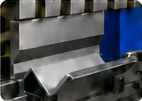
A press brake is a tool used in order to bend sheet metal and uses a punch and die to do this. Although press braking may seem straight forward, it can be quite difficult to remain accurate throughout the process. There are several types of press brakes which deliver different levels of force applied, such as mechanical, pneumatic, hydraulic and CNC to name a few examples.
Sheet metal bending techniques are similar in that their purpose to transform sheet metal structures to the desired forms. However, their operation would be different. Factors such as material thickness, bending size, and bending radius are the main parameters to determine the optimum bending method.
Plate rolling or curving, designates the manufacture of sheet-metal parts that are rolled or curved into shapes that have a smooth radius associated with them. Although sheets of various sizes and thicknesses may be used, curving is the primary manufacturing process for metal bending large pieces of plate.
Roll bending uses either three or four rolls to feed and bend the plate to the desired shape. The positioning of the rolls determines the exact bend of the work. Different curves are obtained by controlling the distance and angle between the rolls. Moveable rolls provide the ability to control the degree of the curve.
Welding
Major challenges
Metal Fabrication Costs and Pricing

Planning for Metal Fabrication
At Novelty Structures, we look at how a fabrication order will move from drawing to delivery. Materials, finishing and transport all affect when the parts will be ready to use. Agreeing these details early gives everyone a clearer plan.
Pre-production review
Share how the part will be used, along with the drawings and required finish. This helps the fabrication review pick up details that could cause extra work later.
For parts that will be galvanised, vent and drain holes need to be agreed with the galvaniser before fabrication. Planning them early helps avoid changes to a finished assembly.
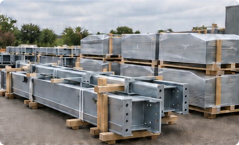
Galvanised supports ready for dispatch
Material sourcing and specification
Confirm the grade, thickness, certificates and lead time before setting a production date, particularly where a drawing calls for a less common material.
Depending on the application, the specification may call for carbon steel, stainless steel, aluminium, wear-resistant plate or specialist steel. The choice needs to reflect the loads, working environment and fabrication process.
Any proposed material change needs to be checked against the design and approved by the customer’s engineering team. This includes its suitability for bending, welding and the intended finish.
Specification → Engineering review → Customer approval
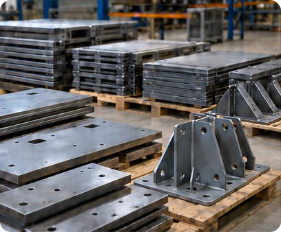
Prepared steel components
Finishing, assembly and logistics
Priority scheduling and staged delivery
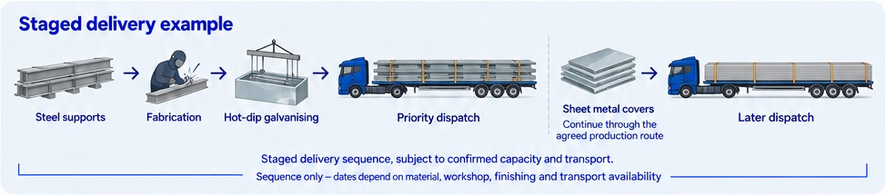
If one group of parts is needed earlier, first check material availability, workshop progress, finishing capacity and transport. These checks provide a basis for agreeing a revised dispatch date.
For example, an equipment manufacturer might need galvanised supports before the sheet metal covers in the same order. A possible approach is to complete and galvanise the supports first, then send the covers later. Agreeing the sequence early gives each team time to plan its part of the work.
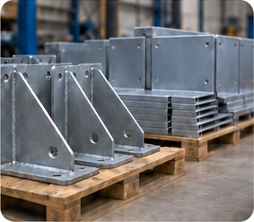
Galvanised supports and sheet metal covers
What to send with your enquiry
Design for metal fabrication
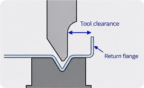
A part can look right in a 3D CAD model and still be awkward to manufacture. In the workshop, each bend needs tooling clearance, every joint needs access, and components must fit together in a workable assembly sequence.
Design for Manufacture (DFM), also called Design for Manufacturing, checks these details before production. In metal fabrication, that means reviewing geometry, material, tooling and assembly together, while there is still time to adjust the design.
Cut → Bend → Join → Inspect → Finish
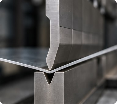
Press brake tooling
Feature constraints in sheet metal fabrication
Resolve these feature constraints during drawing review. A change to flange length or bend radius may allow standard tooling to be used, but it still needs to meet the component’s fit and function requirements.
Bending sequence and movement clearance
Each bend may be feasible on its own, but its position in the sequence can change what is possible next. Review the complete operation before cutting the blank.
Assembly sequence and service access
Assembly access
Install internal brackets and components before closing panels where required. Leave clearance for welding torches, riveting guns, torque tools and temporary clamps.
Inspection access
Complete visual weld inspection and specified non-destructive testing (NDT) before joints become inaccessible. Plan space for inspection equipment.
Service access
A bracket fitted before the side panel may still need replacing later. A removable panel or access door can provide the maintenance access assembly order alone cannot.
Enclosure service access
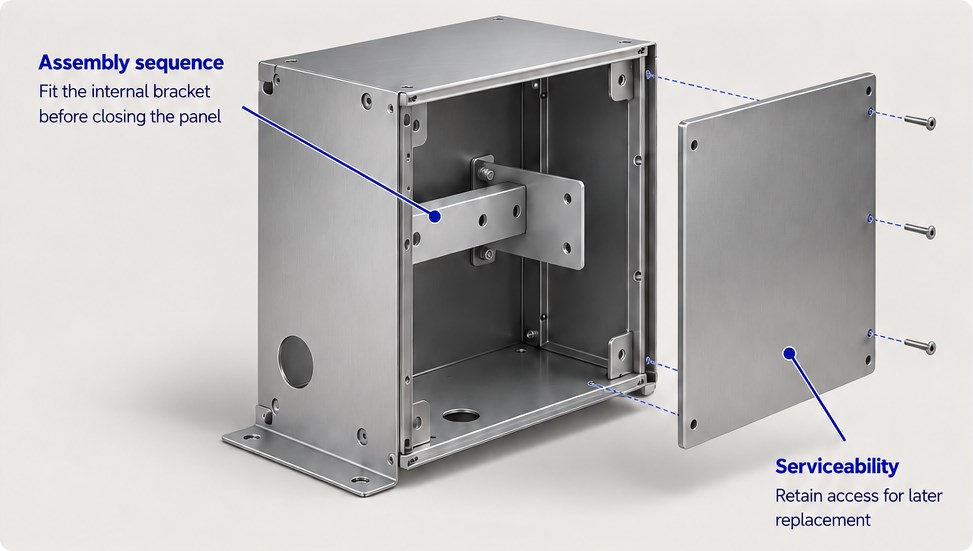
Assembly access and serviceability need separate checks.
Documentation and engineering revision control
Carry agreed instructions into shop travellers and the manufacturing execution system (MES), where used. A drawing update should also reach the people buying material, preparing tooling and carrying out inspection.
A Case Study
A client came to Novelty Structures with drawings for a mounting bracket made from three flat plates joined by four weld seams. The drawings called for each plate to be cut and prepared separately, then positioned and held in place for welding.
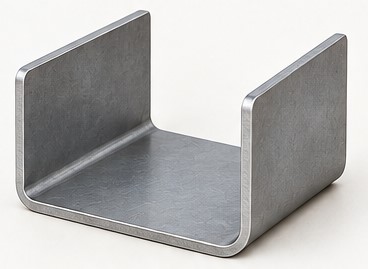
When we reviewed the drawings, we saw an opportunity to form the bracket from a single sheet metal blank. We recommended a CNC-folded design that would remove the four weld seams and the work of aligning the three plates before welding.
Original welded assembly
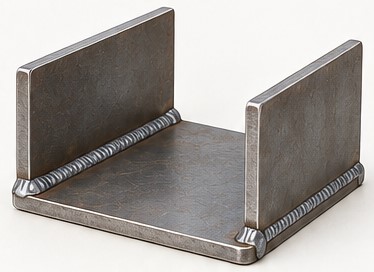
3 plates · 4 weld seams
Proposed CNC-folded bracket
1 blank · formed bends
What the proposed redesign changed
We proposed cutting one flat blank and forming the sides on a press brake. In the original design, the critical dimensions depended on how the plates were fitted and how they moved during welding. In the folded design, they would depend on bend accuracy and springback.
The proposal shifted the work from fitting and welding three plates to forming and checking one component. The table below compares the two production routes. Any time or cost saving would depend on the tooling, inspection requirements and order quantity.

Flat blank for the folded part
Original and proposed production routes
With one blank to track through production, the proposed route would also simplify the bracket’s bill of materials. Tooling, inspection and any work after forming would still factor into the cost comparison.
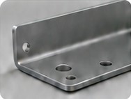
Tooling and machine access
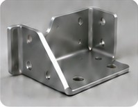
The press brake setup would need enough clearance for each bend and room to turn and remove the bracket.
Tolerance accumulation
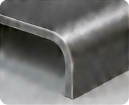
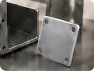
Bend variation and springback would need to stay within the tolerances for the mounting holes, mating surfaces and other critical dimensions.

When we would keep the welded design
We would keep the welded design if the bracket needed different thicknesses or material properties in different areas, or if the available press brake tooling could not form the required shape.
A service requirement to replace part of the assembly separately could also favour a multi-part design.
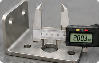
From recommendation to first-article validation
First-article inspection
