Metal Bending

Metal Bending2026-11-05T14:59:07+00:00

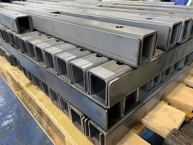
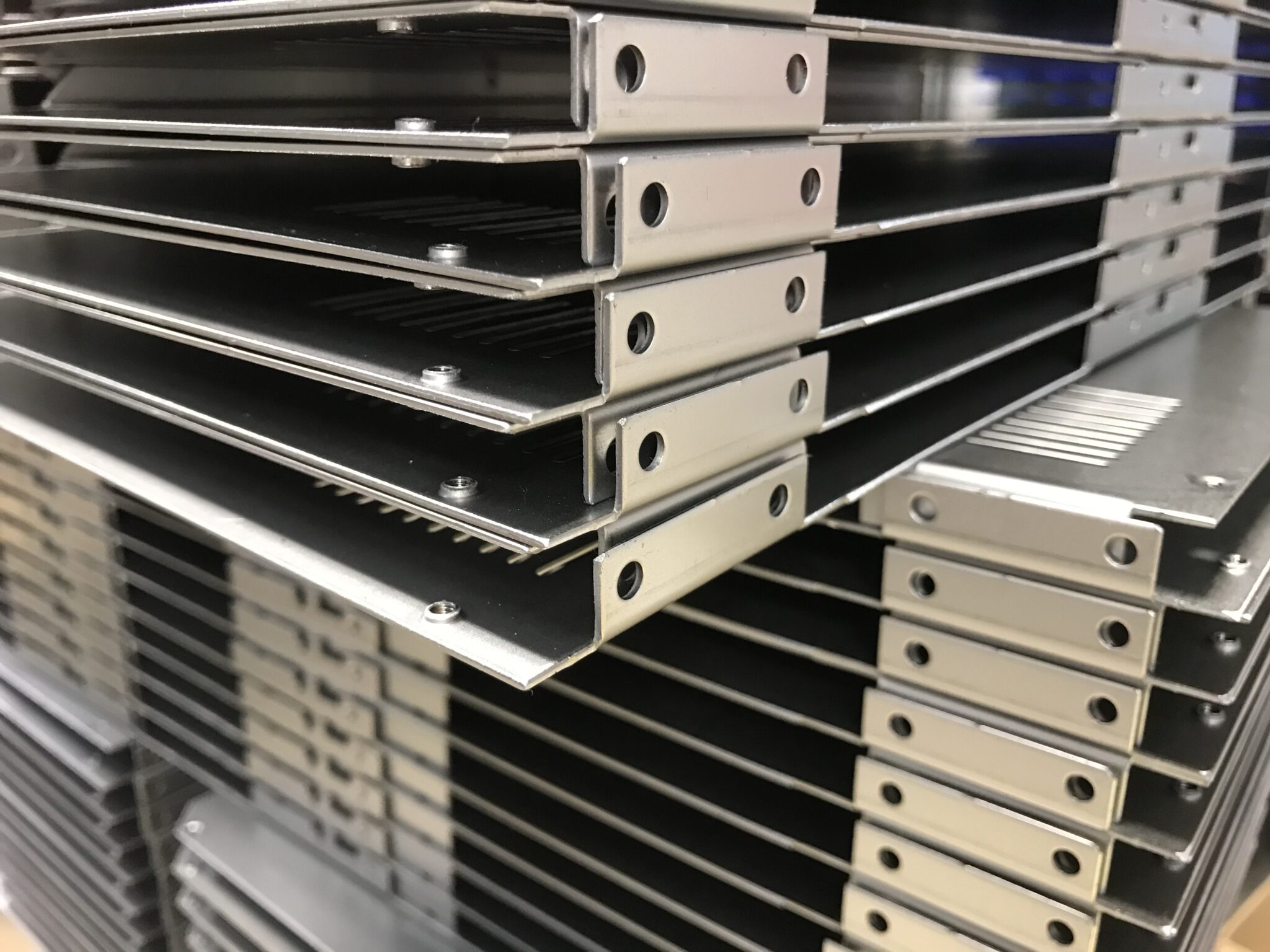
Novelty Structures is an experienced fabricator of Sheet Metal Bending Services for Carbon Steel, Galvanized Steel, Stainless Steel and Aluminium.

Metal bending is one of the most common metal fabrication operation. The sheet metal bending process involves applying a force to a sheet metal part to change its geometry. This force causes stress on the sheet metal beyond its yield strength and permanent physically deform without breaking or failing.

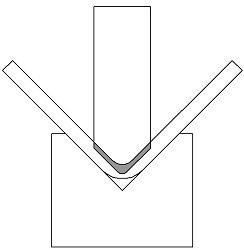
The press brake is a commonly used equipment for sheet metal fabrications. It works by lowering a mould onto a sheet metal work piece positioned on a die, creating the desired form.

The formed bend is dependent upon the tools used, the material yield strength and the material thickness. Setting up a bending operation accurately requires knowledge in the tooling, material, forces and the sequence of the different steps so it requires a skilled operator.
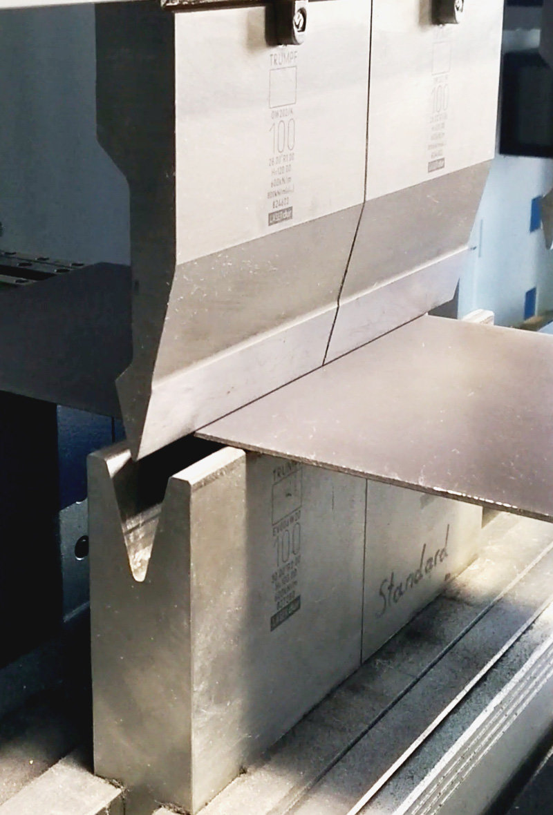
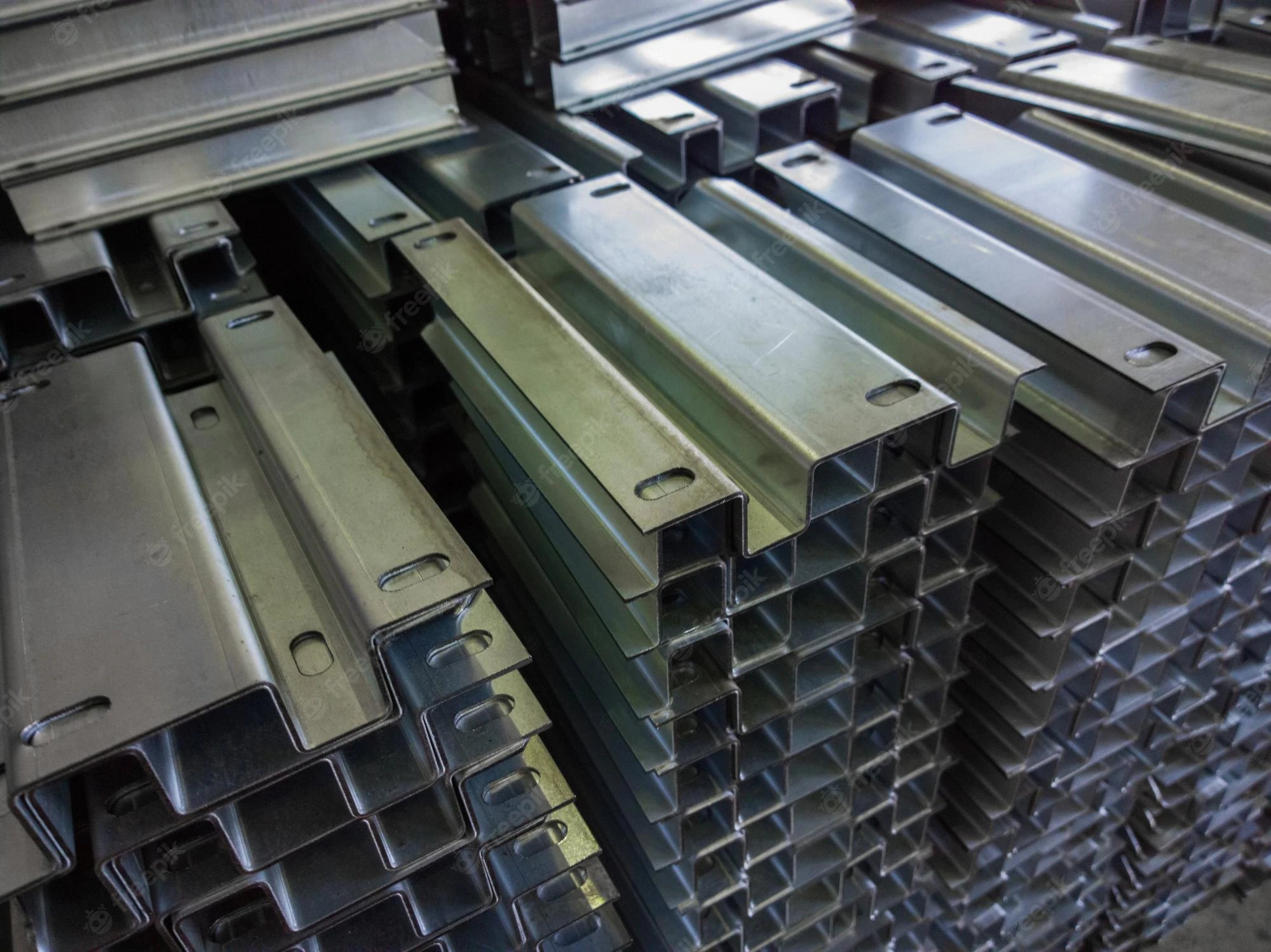
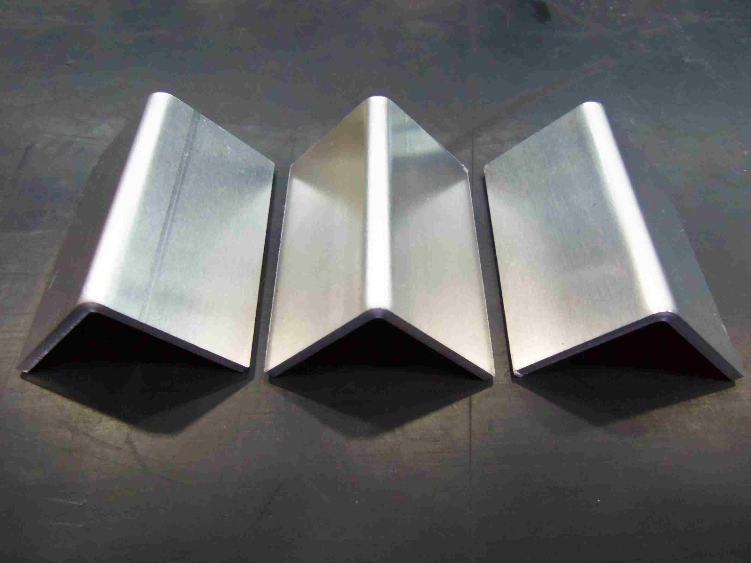
Bending galvanized sheet

Metal Bending Types

Air Bending

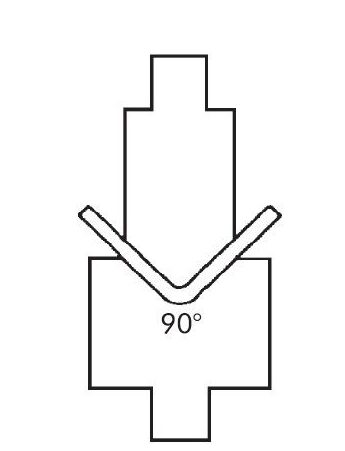
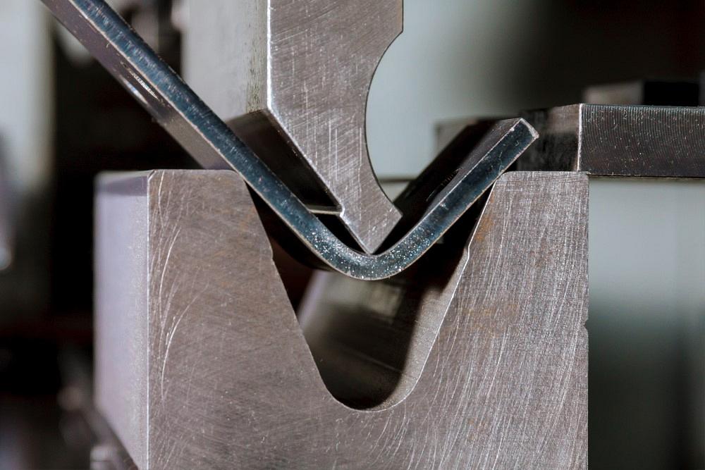
Air bending is the most common type of bending for sheet metals. In this process the work piece squeezed between the outside edges of the die and the punch tip. The punch is then forced past the top of the die into the v-opening without coming into contact with the bottom of the v. The v opening is typically deeper than the angle which is sought in the work piece

Coining

Coining is a type of bending in which the material is stamped between the punch and die. Both the punch tip and the punch actually penetrate into the work piece past the neutral axis under a considerable amount of force

Bottoming

In bottom bending, the punch and die are brought together so the work piece makes contact with the punch tip and the V-opening sidewalls. Since bottom bending uses less force than coining, the work piece does not totally conform to the tooling’s bend angle.

Evolution of Press Brakes

A press brake is a machine that bends sheet metal into predetermined forms.
  •  Mechanical Press Brakes: Ideal for small workshops or tasks with low complexity and limited budgets. Requires skilled operators.

  • NC Press Brakes: A middle-ground option that combines basic automation with better accuracy and speed. Suitable for medium-scale operations.

  • CNC Press Brakes: Best for high-precision, high-volume, and complex bending tasks. They are expensive but deliver unmatched productivity and efficiency.

steel fabrication metal bending
Feature Mechanical Press Brake NC Press Brake CNC Press Brake
Control System Manual operation with basic control Semi-automated, limited program storage. Fully automated with sophisticated control.
Accuracy Moderate accuracy due to manual adjustments. Better accuracy with pre-set programs. High accuracy with automatic real-time adjustments.
Ease of Use Requires skilled operators for precision. Easier to use but still depends on operator setup. Intuitive and user-friendly with graphical interfaces.
Speed of Operation Slower due to manual setup. Faster than mechanical; setup time is reduced. Very fast due to optimized programming and automation.
Flexibility Limited to simple bends and repeatable tasks. Can perform more complex bending operations. Highly flexible for intricate, multi-axis bending.
Cost Low initial cost, high labor cost. Moderate cost. High initial cost but low labor and operational cost.

Guide to Accurate Sheet Bending

Sheet Metal Bending Part

Common Defects

Defect Description QC Measures
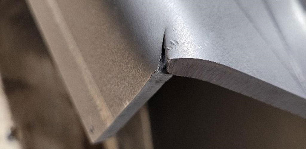
Cracks Cracks at the outer radius of the bend Check bend radius; ensure material ductility.
Wrinkles Ripples on the inner radius Adjust tooling and reduce bend compression.
Spring-back Angle returns slightly after bending Use over-bending or adjust machine settings.
Inconsistent Angles Uneven bend angles across parts Calibrate machine; ensure uniform material.
Surface Scratches Marks or damage to the finish Use protective films or softer die materials.

Bending Different Metals

sheet metal fabrication - bending and laser cutting
Property Carbon Steel Stainless Steel Aluminium
Ease of Bending Moderate (low-carbon) to difficult (high-carbon) Moderate to difficult Easy
Spring Back Low High Low
Force Required Moderate to high High Low
Ductility Moderate to low High (austenitic grades) Very high
Risk of Cracking Low (if low-carbon) Low to moderate High (without care)

Challanges in Metal Bending

Material Challanges


  • Spring-back: Elastic recovery causes incorrect bend angles.

  • Cracking: Outer radius cracking, especially in brittle materials.

  • Thinning: Material weakens at the bend’s outer radius.

Tooling Challanges


  • Tool Alignment: Misaligned tools lead to uneven bends.

  • Tool Wear: Worn tools cause defects like scratches or misalignments.

  • Standard Tool Limitations: Standard dies may not work for custom designs.

Process Challanges


  • Tight Tolerances: Achieving precision in angles and dimensions.

  • Multiple Bends: Errors from cumulative misalignments in complex parts.

  • Surface Damage: Scratches or marks during bending.

Design Challanges


  • Incorrect Bend Allowance: Wrong calculations cause dimensional errors.

  • Complex Designs: Intricate geometries are harder to bend.

Aluminium bending

Human Challanges


  • Operator Error: Mistakes in setup or handling.

  • Communication : Miscommunication between design and production teams.

Metal Bending Case Studies

Case Study 1 — Increasing Mechanical Strength Without Increasing Thickness
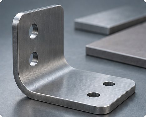
Cold-formed steel bracket with two mounting holes on each flange

Cold-formed steel component

A client required a custom bent component manufactured from 6 mm S235JR steel. The existing design and bending tolerances were suitable for the application, but the client needed to increase the mechanical strength of the component without increasing the material thickness or changing the finished geometry.

The initial proposal was to replace 6 mm S235JR with 6 mm S355JR, providing a higher-strength material while maintaining the same thickness. However, simply selecting a higher-strength steel does not necessarily mean that it will perform in the same way during bending.

Engineering Consideration

Higher-strength steels can require significantly greater bending forces and may be more susceptible to cracking depending on their chemical composition, bend radius, material direction, and forming conditions.

Our engineering team reviewed the application and identified a potential risk of cracking during the bending operation if S355JR was used. Rather than changing the component thickness or compromising the existing bending tolerances, we investigated an alternative material that could provide the required mechanical properties while remaining suitable for the required forming operation.

Solution — S355MC Steel

We recommended testing 6 mm S355MC steel as an alternative. S355MC is a thermomechanically rolled high-strength steel designed for cold forming applications. Its chemical and mechanical properties make it particularly suitable for components requiring both increased strength and controlled forming.

We manufactured test components using S355MC and evaluated the material through the required bending operations. Following successful testing, S355MC was adopted for the application.

Result

The client was able to achieve the following.

  • Increase the mechanical strength of the component
  • Maintain the existing 6 mm material thickness
  • Retain the required component geometry
  • Maintain the required bending tolerances
  • Avoid the cracking risk identified with the original S355JR proposal

Case Study 2 — Replacing Welds With Bends

A client approached us with drawings for a custom metal bracket containing a number of individual sheet-metal sections joined by welded joints. The design was technically manufacturable, but the number of welded connections increased production time, handling, and the number of operations required to produce each component.

Rather than simply manufacturing the part exactly as drawn, we reviewed the design with the client to determine whether the component could be manufactured more efficiently.
Mounting plate assembled with welded side flanges

Welded mounting plate

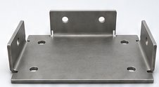
Mounting plate with flanges bent from one piece

Bent mounting plate

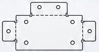
Flat laser-cut mounting plate blank with dashed bend lines

Single laser-cut blank

Engineering Review

Our engineers assessed the geometry of the bracket and identified several locations where separate pieces of sheet metal could be incorporated into a single blank. By introducing additional bends, some of the welded joints could be eliminated altogether.

Solution — Design for Manufacturing (DFM)

Working with the client, we simplified the component and replaced a number of welded connections with additional bending operations. The revised manufacturing route required four additional bending operations, but this significantly reduced the amount of welding required.

Result

The design modification achieved the following.

  • More than 40% reduction in welding operations
  • Four additional bending operations
  • Fewer welded joints
  • Reduced fabrication complexity
  • Reduced welding time
  • A simplified manufacturing process
  • More consistent repeatability between components

Case Study 3 — Managing Spring back

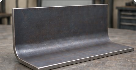
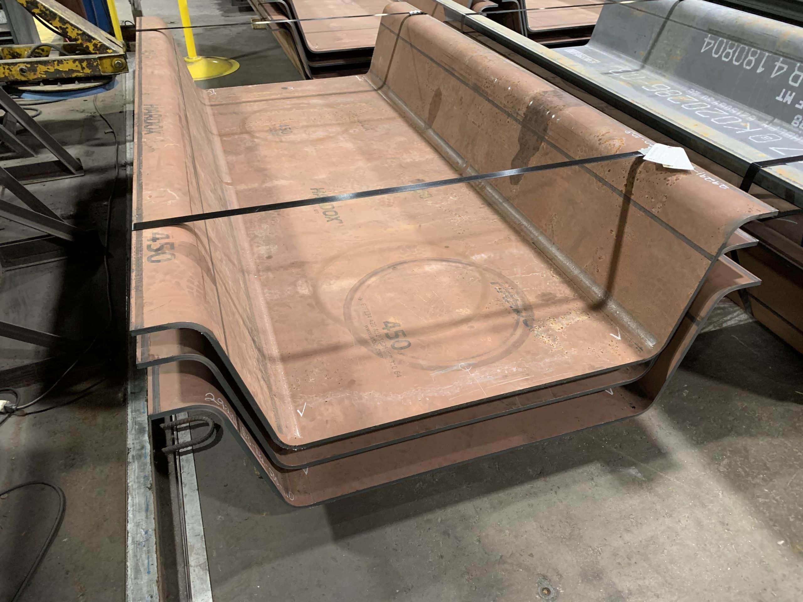
Bent Hardox wear plate for an aggregate chute

Wear-plate spring back

A client in the quarrying and mining sector approached us to manufacture replacement side-liner plates for an industrial aggregate chute. To combat severe abrasive wear, the client requested that the components be formed from 8 mm Hardox 450 wear plate.

While the flat blanks cut without issue, the client’s internal production runs yielded inconsistent bend angles, with completed parts repeatedly opening up beyond acceptable geometric tolerances once released from the press brake.

Engineering Consideration

Bending high-strength and wear-resistant steel is fundamentally different from forming conventional mild steel. Because materials like Hardox possess significantly higher yield strength, they undergo considerable spring back, the elastic recovery of the material after the forming force is removed.

For high-strength steels, achieving precise final geometry requires evaluating the process as a complete, integrated system.

  • Material yield strength and thickness
  • Required inside bend radius and bend angle
  • Press brake tonnage capacity and tool selection
  • Die opening width and punch radius
  • Spring back angle compensation and test-bend validation

Simply transferring standard mild-steel programming, tooling, and die openings to high-strength alloys inevitably leads to out-of-tolerance parts and elevated stress on tooling.

Solution — Dedicated High-Strength Forming Protocol

Our engineering team calculated the specific spring back characteristics of the 8 mm Hardox 450 lot and redesigned the forming parameters.

  • Tooling and Die Adjustment Swapped standard narrow V-dies for a wider V-die opening to reduce the required bending force and prevent material surface micro-cracking.
  • Over bending and Radius Control Applied precise over bending angles into the press brake CNC program to offset the anticipated elastic spring back.
  • Proportional Tonnage Management Utilised high-capacity press brake tooling capable of delivering the required forming force safely.

Prior to the production run, we conducted test bends on sample offcuts from the exact material heat batch to verify the spring back values and calibrate the final stroke depth.

Spring back After Unloading

Conceptual side profile

Solid line — Formed shape under load (in the press)

Dashed line — Final shape after unloading (with elastic recovery)
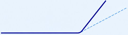
Conceptual side profile showing the bend angle opening after the forming load is removed

Result

By treating the high-strength wear plate as a specialised forming application, we achieved the following.

  • Accurate, repeatable final bend angles within strict assembly tolerances
  • Complete elimination of springback variation across production batches
  • Zero material cracking or surface micro-fracturing along the outer bend radius
  • Reduced wear and tear on press brake tooling
  • Seamless drop-in installation on the client’s mining equipment

Case Study 4 — Avoiding Distortion During Forming
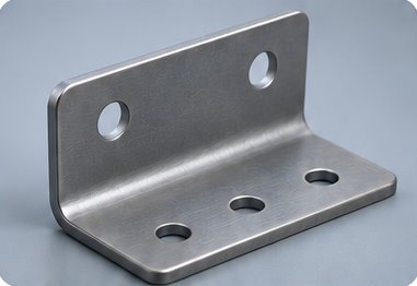
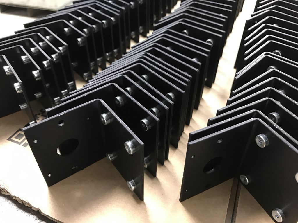
Bent steel mounting bracket with bolt holes on both flanges

Mounting-hole deformation

An industrial machinery manufacturer supplied engineering drawings for a series of heavy-duty motor mounting brackets. The design specified a row of 10 mm precision mounting holes intended to secure a hydraulic pump housing to the machine frame.

The client’s initial prototype batch, produced by laser cutting all features on the flat sheet before forming, resulted in severe assembly failures on the shop floor. During the bending operation, the material stretched near the bend line, pulling the adjacent holes out of round and causing bolt misalignment during machine assembly.

Engineering Consideration

During sheet-metal bending, material within the bend zone undergoes localised plastic deformation, stretching along the outer radius and compressing along the inner radius.

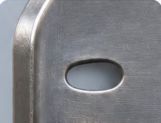
If a hole, slot, or cut-out is located too close to the bend line (within the material’s deformation zone), the forming process pulls the edge of the feature toward the bend. This leads to the following.

  • Elongated, oval, or distorted holes
  • Shifts in centre-to-centre hole pitch locations
  • Interference with mounting bolts, pins, or alignment bushings
  • Assembly misalignment and high scrap rates

The minimal acceptable clearance depends directly on material thickness, material grade, inside bend radius, and die opening width.

Solution — DFM Review and Process Optimisation

Our engineering team performed a Design for Manufacturing (DFM) review to evaluate the relationship between the hole location, material thickness (5 mm), and bend radius.

We presented the client with a two-part solution.

  • Design Optimisation Where frame clearance allowed, we modified the flat blank layout to relocate non-critical mounting holes outside the primary material deformation zone, maintaining a minimum clearance of at least twice the material thickness plus the bend radius.
  • Alternative Manufacturing Sequence For critical fastening holes that could not be moved further from the bend line due to strict spatial constraints, we modified the production sequence to utilise relief slots or punch and ream the holes after the primary bending operation was completed.

Result

The design and process adjustments yielded the following.
  • 100% true-position accuracy and roundness on all critical mounting holes
  • Flawless bolt-hole alignment during hydraulic pump installation
  • Elimination of manual re-drilling, grinding, and scrap parts on the assembly line
  • Consistent component geometry across high-volume production runs
  • A robust manufacturing route optimised for the component’s 3D finished state
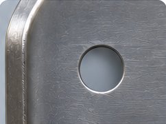
Oval mounting hole distorted near a bend

Hole near bend (distorted or oval)

Circular mounting hole with clearance from the bend

Hole away from bend (remains circular)

How can we help you ?

Sheet Metal Bending is a major Metal Fabrication method and its success depends on the careful selection of contractors.

Novelty Structures stands out as a reliable partner in providing High-Quality Metal Bending Services tailored to demanding industrial needs.

Contact our team to further discuss your needs.

FAQ

What is sheet metal bending?2024-12-27T23:55:09+00:00

Sheet metal bending is a manufacturing process where metal sheets are deformed using tools or machines to create specific shapes or angles. This process is commonly used to produce components for industries like construction, automotive, aerospace, and electronics.

What types of sheet metal materials can you bend?2024-12-27T23:56:06+00:00

We work with a wide range of materials, including:
• Aluminum
• Stainless Steel
• Carbon Steel
• Galvanized Steel

What thickness of sheet metal can you handle?2024-12-27T23:56:44+00:00

We can handle sheet metal thicknesses ranging from thin sheets (0.5mm) to thick plates (up to 40mm). For custom thicknesses, please consult with us to ensure feasibility.

What bending techniques do you use?2024-12-27T23:57:25+00:00

Our bending techniques include:
• Press Brake Bending: Ideal for precise angles and straight bends.
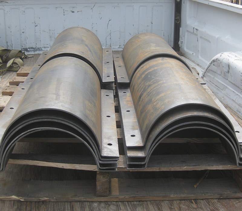
• Roll Bending: Suitable for creating curved or cylindrical shapes.

What is the maximum length of sheet metal you can bend?2024-12-27T23:58:07+00:00

Our machinery can accommodate sheet metal lengths up to 12 meters. For longer lengths, additional solutions may be discussed.

Can you create complex or custom bends?2024-12-27T23:58:48+00:00

Yes, we specialize in custom and complex bending projects. Our advanced CNC-controlled press brakes allow us to produce intricate designs with high precision.

What tolerances can you achieve in bending?2024-12-27T23:59:55+00:00

We typically achieve bending tolerances of ±0.5mm, depending on the material and design complexity. Specific tolerances can be discussed based on your project requirements.

How do you ensure quality in sheet metal bending?2024-12-28T00:00:34+00:00

We use advanced machinery, skilled technicians, and quality control measures such as:

  • Regular inspections during production
  • Dimensional checks with precision measuring tools
  • Compliance with ISO 9001
What is your typical lead time?2024-12-28T00:01:16+00:00

Lead times vary depending on the project complexity and volume. Standard orders are usually completed within 3-10 business days. Rush orders can be accommodated upon request.

Do you offer finishing services after bending?2024-12-28T00:02:01+00:00

Yes, we provide additional finishing services, such as:

  • Powder Coating
  • Painting
  • Polishing
  • Anodizing
  • Hot Dip Galvanization
Do you offer bending for high-strength materials?2024-12-28T00:03:02+00:00

Yes, we are equipped to handle high-strength materials like hardox steel. However, additional considerations for tooling and processes may apply.

How do you prevent surface scratches during bending?2024-12-28T00:03:41+00:00

To protect the material surface, we use protective films, special tool dies, or soft bending tools to minimize scratching or marring for stainless steel.

Do you offer custom tooling for unique projects?2024-12-28T00:04:16+00:00

Yes, we can create custom tooling for unique or highly specific designs to ensure your project requirements are met.

How do you calculate the cost of sheet metal bending?2024-12-28T00:04:57+00:00

The cost depends on:

  • Material type and thickness
  • Quantity of bends
  • Complexity of the design
  • Production volume

Our team will provide a detailed quote after reviewing your requirements.

Metal Fabrication and Welding Works

Gallery

Products

Steel Structures

Plant Engineering Fabrications

Bulk Material Handling Structures 

Steel Buildings

Steel Silos

Hoppers & Chutes

Steel Trusses

Mezzanines & Stairs

Steel Tanks

Services

Laser Cutting 

Metal Bending

Plate Rolling

Machining

Welding

Painting

Go to Top