

Aluminium CNC Machining Service for Custom Parts
- CNC Milling
- CNC Turning
- CNC Grinding
- Heat Treatment
- Coating
- Challenges in Aluminium Machining
- EXECUTIVE OVERVIEW
- 1.1 Background
- 1.2 Phase 1: Functional & Design-for-Manufacture (DFM) Assessment
- 1.3 Phase 2: Comprehensive Decision Criteria Matrix
- 1.4 Phase 3: Financial & Break-Even Analysis
- 1.5 Strategic Takeaways
- 2.1 Background
- 2.2 Phase 1: Identifying Deformation Mechanisms
- 2.3 Phase 2: Diagnostic Process Flow & Tracking
- 2.4 Phase 3: Corrective Engineering Actions
- 3.1 Background
- 3.2 Phase 1: Process Redesign & CNC Integration
- 3.3 Phase 2: Internal Edge Engineering Specification Protocol
Aluminium Machining
Aluminium is widely used in manufacturing due to its unique combination of properties that make it highly versatile and effective for various applications. These characteristics are;
- Lightweight
- High Strength-to-Weight Ratio
- Corrosion Resistance
- Malleability and Workability
- Conductivity
Machining aluminium profiles is relatively inexpensive due to low tool wear caused by aluminium’s low specific cutting force, about one-third of that of steel. Additionally, aluminium allows for higher cutting speeds, further reducing machining costs compared to carbon steel.

Aluminium Machining Operations


Quality Control
How do we price machining works?
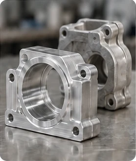
Machining from Solid vs. Aluminium Casting
Selecting an improper manufacturing route for aluminium components can lead to either prohibitive unit costs or premature structural failure. A machinery manufacturer conducted a rigorous technical and financial evaluation comparing two approved manufacturing pathways for a heavy-duty aluminium housing: machining directly from solid stock (plate/billet) versus producing a near-net-shape casting followed by secondary precision machining.
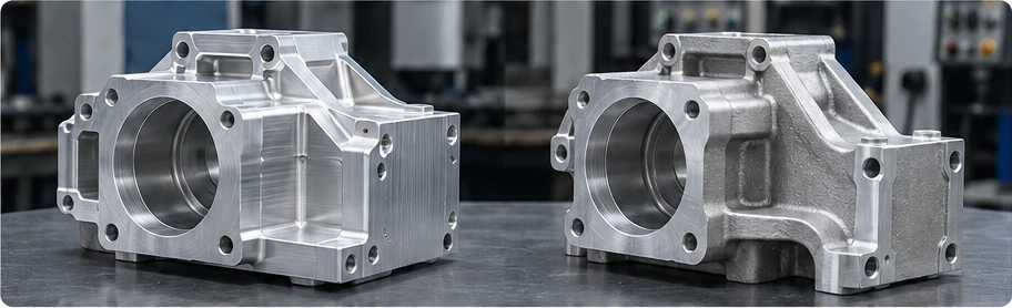
Aluminium housing routes
Functional & Design-for-Manufacture (DFM) Assessment
Before evaluating financial metrics, both pathways were audited against identical engineering and functional standards to establish operational baseline parity:
Operating Conditions: Operating environment, structural load-bearing capacity, tight-tolerance mounting interfaces, surface finish specifications, and strict pressure/leak-tightness requirements were defined.
Alloy & Material Condition: Material specifications and thermal tempers were analyzed independently. Casting alloys were not assumed to be directly interchangeable with machined plate or billet alloys.
Design-for-Manufacture (DFM): The casting route required design alterations, including draft angles, uniform wall thicknesses, and modified corner radii. DFM guidelines (Dynacast) were applied to ensure proper die filling, clean release, and minimal internal porosity.
Casting Process Selection: Sand casting was evaluated against gravity die casting. Lower initial mold setup costs for sand casting allowed casting to be considered at production quantities where gravity die casting tooling costs would be prohibitive.
Comprehensive Decision Criteria Matrix
An eight-factor evaluation matrix was established to systematic compare machining from solid against casting + secondary machining:
| Decision Criterion | Key Evaluation Factors & Engineering Considerations |
|---|---|
| Quantity & Repeat Demand | Evaluate confirmed first order, projected repeat batch sizes, and anticipated design lifecycle before potential engineering changes. |
| Starting Shape | Identify practical stock sizes and material removal volume (machining) vs. net-shape features formed during casting. |
| Remaining Machining | Map post-cast machining required for precision bores, tapped threads, sealing faces, and mating interfaces. |
| Design Stability | Calculate financial exposure of future design alterations across CNC programming, fixtures, patterns, or permanent dies. |
| Material Performance | Validate alloy grade and temper approval across both routes, including mandatory NDT or pressure testing. |
| Quality & Acceptance | Align dimensional tolerances, porosity allowance standards, surface roughness, and leak testing protocols. |
| Delivery Programme | Separate lead times for first-article approval (including tooling build) from ongoing repeat batch lead times. |
| Commercial Commitment | Clarify minimum order quantities (MOQs), tooling ownership terms, maintenance charges, and raw material stock commitments. |
Financial & Break-Even Analysis
The economic evaluation utilised a standard total cost model incorporating one-off initial investments and recurring unit costs:
TOTAL COST FORMULATION
Total Production Cost = One-Off Investment Costs + (Production Quantity × Recurring Cost per Unit)
Scenario Cost Comparison Table
| Production Quantity | Machining from Solid ($1k Setup / $90 Unit) | Casting + Machining ($9k Setup / $50 Unit) | Net Financial Difference |
|---|---|---|---|
| 100 Components | $10,000 | $14,000 | Machining saves $4,000 |
| 200 Components (Break-Even) | $19,000 | $19,000 | Exact Cost Parity |
| 500 Components | $46,000 | $34,000 | Casting saves $12,000 |
VISUAL BREAK-EVEN ANALYSIS
Total Cost Trajectory Visual:
Housing cost comparison
| Production Quantity | Machining | Casting |
|---|---|---|
| Quantity = 100 units | Machining: $10,000 [PREFERRED FOR LOW VOLUME] | Casting: $14,000 |
| Quantity = 200 units | Machining: $19,000 [BREAK-EVEN POINT] | Casting: $19,000 |
| Quantity = 500 units | Machining: $46,000 | Casting: $34,000 [PREFERRED FOR HIGH VOLUME] |
Strategic Takeaways
A Case Study: Post-Machining Distortion
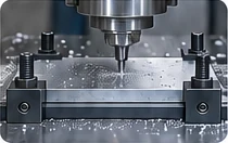
A packaging machinery manufacturer experienced high component reject rates caused by aluminium mounting plates bowing and rocking on assembly surfaces after being removed from machining fixtures. Simply altering cutting speeds failed to address the issue. A structured root-cause investigation was executed to separate material-induced residual stress from fixture-induced clamping distortion.
Identifying Deformation Mechanisms
Two primary failure mechanisms were identified and isolated:
Residual Stress Equilibrium: Internal stresses introduced during mill processing (e.g., rolled plate) remain balanced within the raw stock. Heavy asymmetric material removal (such as pocket milling) disrupts this balance, allowing the plate to warp as stress relaxes.
Clamping Distortion: Forcing a bowed or non-flat blank flat using high-force hydraulic or mechanical clamps causes elastic deformation. When clamps are released post-machining, the component springs back, corrupting the freshly machined flat surface.
DEFORMATION MECHANISM FLOW
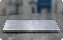
Unrestrained Blank
→
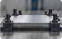
Forced Flat by Clamps
→
Machined Flat
→
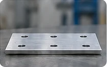
Released: Spring-back Distortion
Key Insight: Altering machining speeds or feed rates alone cannot rectify fundamental material stress relief or elastic clamping spring-back.
Diagnostic Process Flow & Tracking
Components were tracked systematically through the production sequence to identify the exact stage where geometric deviation was introduced:
| Inspection Stage & Process Check | Diagnostic Objective & Findings |
|---|---|
| 1. Measure Raw Blank (Unrestrained) | Establishes whether incoming stock possesses excessive initial bow or twist before processing. |
| 2. Compare Pre- vs. Post-Clamping | Determines whether fixture clamping forces are elastically bending the component prior to cutting. |
| 3. Measure After Roughing & Unclamping | Identifies if substantial material removal triggers internal stress relief and shape movement. |
| 4. Thermal Stabilization Verification | Distinguishes thermal expansion distortion caused by cutting heat from mechanical stress relaxation. |
| 5. Final Unrestrained Measurement | Verifies component flatness against drawing tolerances using agreed multi-point support conditions. |
Corrective Engineering Actions
Staged & Balanced Machining: Alternated rough machining passes between top and bottom faces to equalise stress relief prior to final finishing passes.
Fixture Redesign: Modified fixture support points and reduced clamping forces to prevent elastic deformation during clamping.
Low-Stress Material Stock: Evaluated low-stress cast aluminium tooling plate as a stock substitute for applications requiring extreme flatness.
Thermal Treatment Controls: Avoided unvalidated thermal stress relief, which can compromise the mechanical properties of heat-treated aluminium alloys.
Drawing Acceptance Specs: Updated engineering drawings to clarify whether flatness specs apply unrestrained or under defined assembly torque.
Case Study 2: Eliminating Internal Cross-Hole Burrs
3.1 Background
One of our supplier producing complex aluminium hydraulic components faced critical quality risks due to internal burrs. While external entry points were clean, internal cross-hole intersections contained burrs that risked detaching during operation and blocking downstream hydraulic valves.
INTERNAL CROSS-HOLE CHALLENGE
Internal Passage Intersection Geometry:
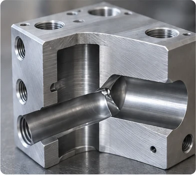
Internal manifold intersection
Outer Surface (Clean & Chamfered)
| Main Hydraulic Bore → | Intersecting Passage [CRITICAL BURR] |
← Cross-Hole Entry ← HIDDEN INTERNAL EDGE |
Technical Risk: Loose internal burrs can contaminate hydraulic fluid and jam downstream valves.
Process Redesign & CNC Integration
The facility originally relied on manual internal deburring followed by an external thermal deburring process. This added logistics overhead, extended cycle times, and created secondary quality risks.
By evaluating internal geometry during early process planning, the engineering team integrated specialised mechanical cross-hole deburring tools directly into the primary CNC cycle. These tools access internal intersections from multiple angles, deburring the internal intersection inside the machine.
Eliminated Offline Thermal Deburring: Completely eliminated the need for third-party thermal deburring services.
Eliminated Manual Deburring: Removed manual scraper operations, ensuring 100% repeatable internal chamfering.
Reduced Production Lead Time: Deburring completed within the standard machining cycle, reducing manifold manufacturing lead time.
Internal Edge Engineering Specification Protocol
To prevent internal burr issues across future manifold programs, a 6-part specification framework was adopted :
| Protocol Step | Implementation Requirement & Best Practice |
|---|---|
| 1. Internal Edge Identification | Explicitly mark all internal cross-hole intersections and rear exits on 2D/3D drawings rather than using generic ‘remove all burrs’ notes. |
| 2. Edge Condition Definition | Distinguish basic burr removal from precise chamfer or radius requirements, particularly near valve-seating faces. |
| 3. Access Geometry Modeling | Provide detailed 3D CAD section views showing complete internal intersection geometry for CNC toolpath programming. |
| 4. Inspection Protocol | Establish non-destructive inspection methods, such as borescope inspection or destructive sample sectioning for initial production batches. |
| 5. Cleaning & Flushing Standards | Specify high-pressure internal flushing requirements separately from deburring to guarantee complete chip removal. |
| 6. Quotation Transparency | Incorporate internal deburring and cleaning explicitly into the machining quote scope to ensure total cost visibility. |
BEST PRACTICE CHECKLIST
FAQ
Contract CNC machining refers to outsourcing precision manufacturing tasks to a specialized provider. These services involve computer-controlled machining processes to produce high-quality parts or components from various materials, including metals, plastics, and composites.
Our facility utilizes a wide range of CNC machines, including:
- CNC mills
- CNC lathes
- 5-axis machining centers
- Swiss-style lathes
- CNC routers
Lead times depend on project complexity, material availability, and order volume. Prototyping projects often take 1-3 weeks, while production runs may take 4-8 weeks. Expedited services are available for urgent needs.
Yes, we offer a variety of finishing services, including:
- Anodizing
- Powder coating
- Polishing
- Sandblasting
- Heat treatments
- Plating (e.g., chrome, nickel)
Yes, we have CNC machines capable of handling large parts and assemblies. Our facilities include machines with extended work envelopes and multi-axis capabilities to accommodate oversized or complex components.
Yes. We can machine custom threads (both internal and external) and create specialized features such as undercuts, thin walls, deep pockets, and complex contours based on your specifications.
We ship globally using a variety of carriers. Depending on your location and urgency, we can provide standard shipping, expedited shipping, or freight options for large orders.
Yes, we can combine CNC machining with other processes such as injection molding, die casting, 3D printing, and metal stamping for a complete manufacturing solution.
Yes, our precision CNC machines are equipped to produce small, intricate components with features like micro-holes, fine threads, and detailed engravings.
Yes, to ensure manufacturability, consider the following:
- Avoid overly thin walls or deep pockets.
- Specify radii for inside corners.
- Use standard hole sizes where possible.
- Minimize excessive tolerances unless necessary.
If defective parts are identified, we will replace them free of charge. We work closely with our clients to address any issues promptly and improve future production runs.
Yes, we provide post-production assembly services, including mechanical assembly, fastening, and packaging, depending on your project’s needs.

How can we help you ?
Alumunium Machinining Services are indispensable to various industries and their success depends on the careful selection of contractors.
Novelty Structures stands out as a reliable partner in providing high-quality Alumunium CNC Machining services tailored to demanding industrial needs.

