

Novelty Structures provides high-precision CNC machining services for custom component manufacturing.
- Custom CNC Precision Machining
- Precision Machining Operations
- Materials
- Quality Control
- Precision Machining Advantages
- Precision Machining Applications
- Post Machining Processes
- How can we help you ?
- FAQ
- Case Study: Solving a Deforming Bearing Housing in Precision Machining
- Case Study: Why Individual Measurements Aren’t Enough for a Perfect Fit
- Define Critical Dimensions After Surface Finishing
Custom CNC Precision Machining
Precision machining is a specialized branch of manufacturing that focuses on producing parts with incredibly tight tolerances. Precision machining prioritizes minute detail, accuracy, and repeatability.
Using computer-aided design (CAD) and computer numerical control (CNC) technologies, precision machining achieves levels of precision that traditional methods cannot. The components are often critical in applications where even slight variances can affect safety and performance.

Precision Machining Operations


Materials
Metals

Plastics

Quality Control


A Case Study: Solving a Deforming Bearing Housing in Precision Machining
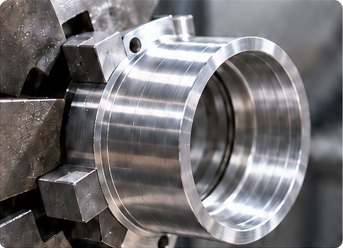
Bearing housing workholding
Measure clamped → Release pressure → Measure unclamped
The Problem
We were asked to manufacture thin-walled aluminum bearing housings that required a tight-fitting inner hole (bore). While the part was clamped tightly inside the lathe, the bore measured perfectly against the engineering drawing.
However, as soon as the machinist released the chuck and removed the part, the housing sprang back into its natural shape. The unclamped bore was distorted and out-of-round, making it impossible to fit the bearing properly during final assembly.
The Investigation
The team’s initial reaction was to adjust the cutting tool settings to make the hole slightly bigger or smaller. They quickly realized this would not solve the problem. Adjusting tool offsets only changes where the tool cuts—it cannot fix a hole that is being machined while the metal is physically squeezed out of shape.
To pinpoint the exact cause, the engineers conducted a step-by-step test:
- 1They measured the bore diameter while the component was clamped in the chuck.
- 2They measured the exact same spot immediately after releasing the clamping pressure.
The comparison proved that the chuck pressure was crushing the thin aluminium walls during machining. They also checked room temperatures and verified their measuring instruments to rule out heat expansion or tool errors.
The Solution
To stop the workholding equipment from distorting the housing, the team modified their machining approach:
- 1Custom Soft Jaws: They replaced standard hard clamps with custom-machined “soft jaws” shaped to match the exact outer profile of the housing. This distributed the clamping force evenly over a large surface area instead of crushing specific points.
- 2Better Contact Points: They shifted the grip location away from the delicate thin wall and clamped onto a thicker, more rigid section of the part.
- 3Calibrated Clamping Pressure: They reduced the chuck pressure just enough to stop deforming the metal, while ensuring it remained tight enough to safely hold the part under cutting forces.
- 4Two-Stage Machining: Instead of finishing the hole in one go, they split the process. They completed a rough cut first, released and re-clamped the part to relieve built-up stress, and then performed a final, delicate finishing cut.
Another Case Study: Why Individual Measurements Aren’t Enough for a Perfect Fit
The Problem
An industrial equipment manufacturer ordered a batch of custom bearing housings for a new assembly line. The engineering drawing gave exact dimensions for every individual feature: the diameter of the inner hole (bore), the thickness of the mounting plate, and the spacing of the bolt holes.
When the parts arrived, quality control checked every dimension. Every hole and surface matched the drawing’s size specifications. However, when the assembly team bolted the housing onto the machine frame and tried to slide the driveshaft into place, the shaft jammed tight. Despite every individual measurement being correct, the assembly wouldn’t work.
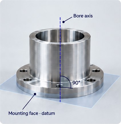
Bore alignment and mounting datum
The Investigation
The team brought the housing back to the workbench to find out why a “perfect” part was failing in real life:
- 1They checked the inner bore diameter—it was exact.
- 2They checked the flat mounting plate—it was flat.
- 3They measured the angle between the two—and found the issue.
While the hole was the right size and the plate was flat, the hole was drilled at a very slight tilt relative to the mounting plate. Because the drawing only specified individual sizes, the machine shop had no way of knowing how the parts worked together. Without a defined reference surface (a “datum”), the machinist clamped the part in a way that accidentally tilted the hole relative to where the housing sat on the machine frame.
The Solution
To fix the issue, the engineering team revised their blueprint before placing the next order:
- 1Established Reference Points (Datums): They clearly marked the flat mounting face as the main reference surface on the drawing. This told the machinist that every other feature needed to be measured relative to that specific face.
- 2Defined Feature Relationships: Instead of just giving the hole size, they added a simple geometric requirement: the center line of the bore had to sit at a perfect 90° angle to the mounting plate.
- 3Mapped Mating Parts: The team reviewed every surface that touched another component (the frame, the bolts, and the shaft) and made sure those critical connection points were explicitly controlled on the drawing.
The Outcome
The machine shop used the revised drawing to set up their cutting tools around the designated reference face. When the new batch of bearing housings arrived, they bolted flat against the machine frame, and the driveshaft slid smoothly through the center of the bearing with zero friction or binding.
The Takeaway
A list of sizes doesn’t guarantee that parts will fit together in service. For precision parts to work in an assembly, technical drawings must specify how critical surfaces relate to one another using real-world reference points—rather than leaving alignment decisions up to the machinist.
Define Critical Dimensions After Surface Finishing
A close-fitting component needs a clear dimensional requirement for its final supplied condition. Coatings and surface treatments can affect dimensions, so a part measured after machining may fit differently after finishing.
For CNC precision machining enquiries, specify whether critical dimensions apply before or after the stated treatment. Identify any bores, threads, locating surfaces or contact faces that require particular attention.
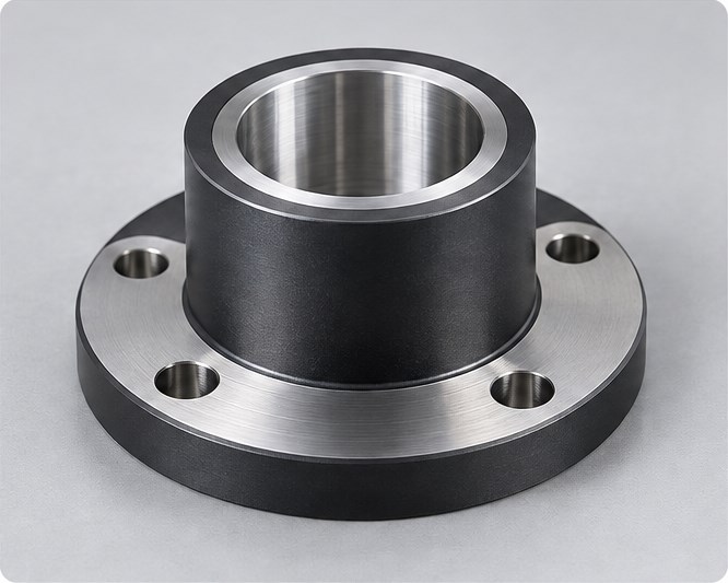
Selective finishing on a bearing housing
| Detail to specify | Why it matters |
|---|---|
| Required finish and applicable specification | Gives the supplier a defined treatment requirement rather than a general description. |
| Dimensions required after finishing | Connects acceptance checks to the condition in which the component will be supplied. |
| Areas requiring masking or exclusion from treatment | Makes selective finishing requirements visible during quotation and process planning. |
| Surface texture on functional faces | Distinguishes requirements for mating or sealing surfaces from general appearance. |

How can we help you ?
Precision CNC machining services support demanding industrial applications, making the selection of a capable machining partner essential.
Novelty Structures supplies high-quality precision CNC machined parts tailored to demanding industrial needs.
FAQ
Contract CNC machining refers to outsourcing precision manufacturing tasks to a specialized provider. These services involve computer-controlled machining processes to produce high-quality parts or components from various materials, including metals, plastics, and composites.
Our facility utilizes a wide range of CNC machines, including:
- CNC mills
- CNC lathes
- 5-axis machining centers
- Swiss-style lathes
- CNC routers
Lead times depend on project complexity, material availability, and order volume. Prototyping projects often take 1-3 weeks, while production runs may take 4-8 weeks. Expedited services are available for urgent needs.
Yes, we offer a variety of finishing services, including:
- Anodizing
- Powder coating
- Polishing
- Sandblasting
- Heat treatments
- Plating (e.g., chrome, nickel)
Yes, we have CNC machines capable of handling large parts and assemblies. Our facilities include machines with extended work envelopes and multi-axis capabilities to accommodate oversized or complex components.
Yes. We can machine custom threads (both internal and external) and create specialized features such as undercuts, thin walls, deep pockets, and complex contours based on your specifications.
We ship globally using a variety of carriers. Depending on your location and urgency, we can provide standard shipping, expedited shipping, or freight options for large orders.
Yes, we can combine CNC machining with other processes such as injection molding, die casting, 3D printing, and metal stamping for a complete manufacturing solution.
Yes, our precision CNC machines are equipped to produce small, intricate components with features like micro-holes, fine threads, and detailed engravings.
Yes, to ensure manufacturability, consider the following:
- Avoid overly thin walls or deep pockets.
- Specify radii for inside corners.
- Use standard hole sizes where possible.
- Minimize excessive tolerances unless necessary.
If defective parts are identified, we will replace them free of charge. We work closely with our clients to address any issues promptly and improve future production runs.
Yes, we provide post-production assembly services, including mechanical assembly, fastening, and packaging, depending on your project’s needs.


