
Novelty Steel Uses Various Types of Steel Pipes for Piping Fabrication of Pressure And Non-Pressure Applications.
Table of Contents
1. Introduction to Steel Pipes
In general terms, a pipe or tube refers to a circular hollow section with an outside diameter (OD), inside diameter (ID), and a corresponding wall thickness (WT). Pipes and tubes are utilized for the transportation of fluids and gases from one location to another, typically under the influence of an external force, often generated by a pump or static head.
Pipes are usually manufactured in accordance with well-established industrial standards. Tubes, on the other hand, may be made to custom sizes with a broader range of diameters, wall thicknesses, and tolerances. Additionally, the term “tube” is applicable to non-cylindrical sections, such as square and rectangular sections.
2. What is the difference between pipe and tube?
The primary distinction between pipes and tubes lies in the method of specification. Pipes are specified by “nominal pipe size” (NPS) and schedule (WT). NPS is a size standard established by the American National Standards Institute (ANSI), and it should not be confused with thread standards like NPT.
NPS ranges from 6 to 300 mm (1/8″–12″), with hypothetical diameters between OD and ID (neither equal to OD nor ID). For NPS 350 mm (14″) and above, measured ODs correspond to NPS in inches. Pipes of a specific NPS are available in various WT schedules, such as Sch 40, Sch 60, STD, XS, and XXS.
This specification approach has led to the misconception that NPS refers to ID for smaller pipes (6–300 mm or 1/8″–12″), which is not accurate. This confusion arises from the way the standard was initially defined. The standard OD was originally set as the ID of the pipe in inches plus twice the WT of a common thickness used extensively at that time. This methodology was applied to sizes up to 12″. However, as larger pipes came into production, it was decided to equate the OD of the pipe to match the nominal size when expressed in inches, resulting in varying IDs for all sizes from NPS 14″ to 48″. This means that the OD of pipes does not change regardless of the WT for any pipe in the range of NPS 6–1,200 mm (1/8″–48″).
Tubes, on the other hand, are customarily specified by their OD and WT, expressed in Birmingham Wire Gauge (BWG) or in thousandths of an inch (Thou). Tubes tend to be more expensive than pipes due to tighter manufacturing tolerances. Tubes are commonly used in heat exchangers, instrument lines, and small interconnections on equipment such as compressors and boilers.
Here is a comparison of the differences in dimensions for a 15 mm (1/2″) pipe and tube:
Pipe (NPS ½″ Sch 40): OD 21.3mm, WT 2.77mm
Tube (1/2″×1.5): OD 12.7mm, WT 1.5mm
3. Types of Steel Pipes
3.1 Seamless Steel Pipes
A seamless steel pipe is a type of pipe that is manufactured from a solid round steel billet. The production process involves heating the billet and piercing it to create a hollow tube without any welding joints. Seamless pipes produced through extrusion or rotary piercing. As a result a continuous and uniform structure along the length of the pipe is achieved.
The obvious advantage of seamless pipes is that they don’t have a weld seam. Traditionally, weld seam in pipes has been viewed as a weak spot, vulnerable to failure and corrosion. Thickness variations possible. Since weld is not present, pipe is more uniform.
Although there should be no issues with the seams of welded pipes supplied by reputable manufacturers, seamless pipes prevent any possibility of a weak seam.
Seamless pipes have better dimensional control such as in ovality, or roundness, than welded pipes.
The major disadvantage of seamless pipes is that their internal surface finish is a major issue and possibility of more surface defects. Also Longer lead time required often resulting in significant price fluctuation during the lead time.
3.2 Welded Steel Pipes
The process of manufacturing welded pipes starts shaping a steel strip, obtained in coil form by slitting a wide plate coil into the required width. This strip is then formed into a multiple-length shell using a series of forming rolls. The longitudinal edges of the shell are continuously joined through high-frequency resistance or induction welding. Subsequently, the welded multiple-length shell undergoes electrical heat treatment, sizing, and cutting to specified lengths using a flying cut-off machine.
The cut pipes are then subjected to straightening, squaring, or bevelling at both ends as needed. Following these steps, the pipes undergo non-destructive testing (NDT), inspection, and hydrostatic testing.
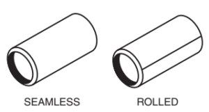
Seamless and Welded ( Rolled) Pipes
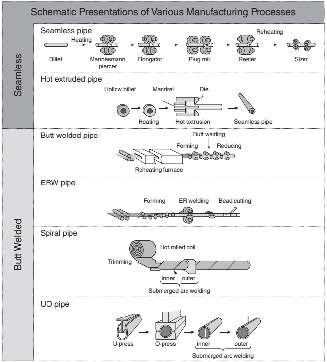
Schematics of pipe manufacturing processes (JFE 21st Century Foundation, 1991)
Knowledge Hub

