Pressure Vessel Manufacturing

Pressure Vessels are fabricated involving assembling various components like Heads, Shells, Cones, and Nozzles.

The fabrication steps, from material identification to welding and painting, are meticulously followed to ensure the integrity and reliability.

1. Components of Pressure Vessels

Pressure vessels comprise various components, as illustrated in the below Figure 1. Manufacturing processes are adopted based on the shape of these components, and these methods must strictly adhere to the provisions of the prevailing code. 

 Pressure Vessel Components

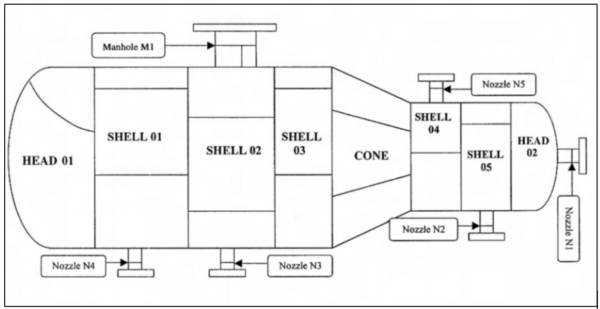
Figure 1 : Pressure Vessel Components

The major components of a pressure vessel are;

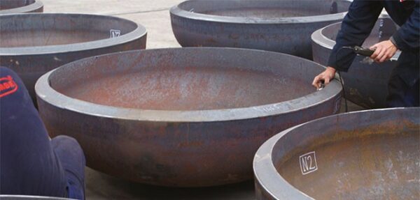
  • Heads or dished ends
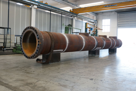
  • Shell 
  • Cones or reducers
  • Nozzles, manholes, saddle supports, skirt supports, leg supports, lifting lugs,
    platform and ladder supports

The production of heads and cones is more challenging than that of shells because of the complexity in controlling their dimensions. Unlike shell sections, which can be precisely controlled, the dimensions of heads and cones pose greater difficulty. Consequently, in vessels featuring dished ends or cones, it is recommended to manufacture these components first, ensuring they comply with code tolerances. Subsequently, the shells are crafted to match and complement these heads and cones.

2. Forming of Pressure Vessel Components

Forming involves changing the size or shape of a part through force, generating stresses above yield strength but below fracture strength. The temperature during fabrication categorizes forming as hot, warm, or cold. Hot forming is above recrystallization temperature, warm is above room temperature but below recrystallization, and cold is well below recrystallization (e.g., room temperature). In pressure vessel manufacturing, specific forming processes include pressing, spinning, and bending.

2.1 Pressing

When employing the pressing process for manufacturing, especially for smaller parts like domes and pipe caps, the plate is gradually shaped by local pressing, covering the entire blank progressively. The choice of this method depends on factors such as plate thickness, desired curvature radius, material properties, machine capacity, and die availability. This process is relatively slow and may result in local deformations, necessitating thorough inspection.

In cold pressing, work hardening can lead to surface cracks, requiring liquid penetrant testing (LPT) for surface examination. Heat treatment may be necessary between cold forming stages to address severe work hardening effects, determined by calibrated extreme fiber elongation expectations. In hot pressing, meticulous attention is crucial for proper heating, heat maintenance during the process, and subsequent cooling, as they significantly impact the material’s grain structure. Temperature, heating/cooling rates, and other parameters are determined based on the material specification and forming requirements outlined in the applicable code.

2.2
Spinning

This process is utilized for crafting various dished ends, including torispherical, ellipsoidal, toriconical, and hemispherical shapes. One notable advantage is that it doesn’t require dies, making it the fastest method for manufacturing dished ends. Initially, a hole of approximately 20 mm diameter is created, typically through drilling, at the center of the blank. The crown portion of the dish is then formed using local pressing. Subsequently, the partially formed blank is loaded onto a spinning machine, and while spinning, the final shape is achieved with adjustable guide rollers.

The guide roller movement progresses from the crown area towards the straight flange through the knuckle area. Continuous spinning ensures a surface free from local deformations, although spinning lines may appear, especially at the knuckle portion where maximum deformation occurs. Depending on factors such as blank thickness and machine capacity, the process is executed either in a cold or hot manner.

2.3 Bending

Although commonly referred to as rolling, this process is not actual rolling. Rolling involves thickness reduction in a plate, while bending imparts curvature to the plate without reducing its thickness. Bending is typically achieved using a three- or five-roll plate bending machine of sufficient capacity. The three-roll plate bending machine is widely used in the fabrication industry.

In the process, the plate is passed through the rollers after both edges are pressed to the required radius, a step known as pre-bending. This pre-bending is achieved by pressing the two power/drive rollers against the top idle roller, bending the plate edges. Once the edges are appropriately pressed, the entire length of the plate is passed through the rollers to introduce curvature in steps. For large diameters and relatively thin thickness (up to 10 mm), curvature can be applied in one pass. However, if the thickness is substantial and the diameter is small, bending is carried out in stages.

3. Fabrication of Pressure Vessel Components

3.1. Material Identification

The initial step in manufacturing any component involves identifying the material to be used, and the material test certificate is crucial for this purpose. While incoming inspection at workshop assumes detailed scrutiny, it is essential to verify material specifications and heat numbers stamped on the plate against those in the certificate and the drawing specifications.

If specific pressure parts like dished ends or cones are marked on the plate, this identification must be transferred to all smaller components. Scrap plates, along with the inspector’s personal stamp, should also be identified. A certificate confirming this identification, preferably with sketches for reference, is advisable. The identification process should be conducted for each pressure part. Material identification stamps, if possible, should be on the outside of the vessel for easy verification, particularly for uninsulated vessels. Low-stress stamps are recommended for vessel stamping, with a caution against hard punching.

3.2. Dished Ends

Semi-Ellipsoidal Dished Ends:

  • This type is widely used in the pressure vessel industry.
  • The inside depth of the dished end, excluding the height of the straight face, is half the inside radius, making it a 2:1 ellipsoidal shape.
  • Manufactured by cold or hot pressing, and sometimes a combination of pressing and spinning.
  • For smaller and thinner dished ends (diameter up to around 700 mm with thickness over 10 mm), cold or hot pressing is used. Larger dished ends employ a combination of pressing and subsequent spinning.
Dished Head

Photo 1: Dished Head

Hemispherical Dished Ends:

  • Produced similarly to 2:1 ellipsoidal heads.
  • For spinning, a hole (20 to 30 mm in diameter) is provided at the center of the blank. If nozzles are to be attached, the opening is enlarged accordingly, or it is plugged if not needed.
  • The plugging process involves welding or using a plug with matching thickness. The hole is slightly enlarged to a maximum diameter of 60 mm, as specified in UW 34.
  • Preferred welding configurations include a single V toward the inside for thickness below 16 mm and an unequal V of 2/3 t and t with the major V from inside for larger thickness.

Torispherical Dished Ends:

  • Similar in shape to 2:1 ellipsoidal.
  • Manufacturing methodology is the same as either hemispherical or 2:1 ellipsoidal heads.

In conclusion, dished ends are manufactured using pressing and spinning methods, with specific techniques applied based on size, thickness, and design considerations. The details include provisions for attaching nozzles and the preferred welding configurations for different thicknesses.

3.3 Shells

When the length of the plate is sufficient to accommodate the full circumference of the shell, it is the preferred condition as it allows for only one longitudinal seam in the shell. The manufacturing process involves the following steps:

  • Plate Preparation:
    • The plate is initially cut to the required length and breadth, and then all four sides are cut with a bevel as per the drawing.
    • Oxyacetylene flame cutting is used for carbon steel plates, while the plasma-arc process is employed for stainless and high alloy steels.
    • Cut edges are ground back to sound metal by at least 1 to 1.5 mm to remove adversely affected material in the cut zone. This helps prevent oxidized metal from entering the weld pool, ensuring weld compatibility with the base metal.
    • The dressed edges are examined for defects like laminations and irregularities on the bevel due to incorrect cutting parameters
  • Plate Rolling:
    • The plate is pre-bent at both ends and then completely bent to the required diameter using a plate bending machine.
    • Depending on the curvature needed, the plate is passed through the roller multiple times, achieving curvature in stages to minimize elongation.
  • Quality Check:
    • Various parameters of the shell section, such as diameter, profile, out-of-roundness, etc., are checked.
    • If all parameters are found satisfactory, the shell is taken for the fit-up of the longitudinal seam.
Pressure Vessel Shell

Photo 2 : Pressure Vessel Shell

This process ensures meticulous preparation of the plate, including cutting, bevelling, and bending, to meet the required specifications and quality standards. The careful examination of cut edges and the use of appropriate methods contribute to the integrity of the subsequent welding process.

When the length of a single plate is insufficient for creating the entire shell, two or more plates are joined together in a plate-to-plate fashion to achieve the required shell length. 

The plate is bent only after completing the weld on both sides. If radiographic examination of the seams is required, it is performed after the bending process. This sequential approach ensures that the welding is completed before bending, and any necessary corrections or adjustments are made to maintain the required specifications and quality standards.

3.4 Cones 

Cones are manufactured using two primary methods, depending on their size and geometry:

  1. Plate Bending Method:
    • Suitable for cones with a relatively small bevel angle and a large diameter.
    • Produced in a plate bending machine where the pressure rollers at both ends can be independently adjusted.
    • This process requires skilled operators compared to shell bending.
    • In some cases, when plate size and machine capacity allow, the cone can be made in one piece.
  1. Pressing Method:
    • Used when the thickness of the cone is larger and the diameter is smaller.
    • Pressing is carried out with matching male and female dies, either in full length or in pieces based on machine capacity.
    • Manufacturing eccentric cones is more challenging than concentric cones; hence, eccentric cones are typically made in two halves if the machine capacity permits.

The choice between these methods depends on factors such as the size of the cone, bevel angle, available plate size, and machine capacity. The pressing method is employed for cones with specific thickness and diameter characteristics, with eccentric cones requiring more careful handling and often manufactured in two halves for practical reasons.

4. What is Novelty Steel Offering
?

Novelty Steel offers contract pressure vessel fabrication for various industries.

Knowledge Hub