
Novelty Steel Is An Experienced Manufacturer of Piping Spool Fabrication for Both Carbon Steel and Stainless Steel Applications.
All spool fabrications take place in our state of the art manufacturing facilities in Turkey.
Table of Contents
1. General Considerations for Piping Spool Fabrication
- Prior to the installation of pre-fabricated spools, a thorough cleaning process is essential. Both the inside and outside of the piping components should be cleaned using suitable means. The cleaning process must involve the removal of all foreign matter, including scale, sand, weld spatter, chips, etc. It’s important to note that specific fluid services may have unique cleaning requirements, which should be followed as indicated in piping material specifications, isometrics, or in the line list.
- If slopes are specified for various lines in drawings, it is crucial to maintain the specified slopes as required. Slopes are designed for draining the line and are particularly critical in hydrocarbon or other inflammable or toxic liquid-carrying lines.
- To accommodate pipes passing through concrete walls or floors, it is important not to cast the pipes directly into the concrete. It is recommended to pass the pipes through cast-in sleeves. These sleeves should be constructed using standard weight pipes and must have an internal diameter that provides a 12 mm radial clearance to the passing flange. This clearance includes any lagging associated with the flange, where applicable.
- In situations where pipework needs to pass through a floor plate and grid mesh, a 75 mm high collar should be welded to the floor plate or mesh. The internal diameter of this collar should be large enough to provide a minimum clearance of 25 mm to the passing flange. The welded collar acts as a protective barrier, ensuring that the pipework passes through the floor plate and grid mesh without causing damage or friction.
- During the installation of stainless steel piping in close proximity to carbon steel piping, special precautions must be taken to prevent direct contact between stainless steel and carbon steel at any stage of construction. Additionally, carbon steel blinds, spades, and caps should not be used for stainless steel pipes and components, even as a temporary arrangement
2. Field Welding
There are two types of field weld joints: butt-welded groove and socket (fillet) welded joints. Butt and socket welds are pressure-retaining welds in piping, while fillet welds are necessary for attaching structural members to the piping to provide rigidity or flexibility based on configuration.
The bevel preparation for field weld joints is the same as that used in shop fabrication of piping spools. Any differences encountered during fit-up may require significant force to align the field weld joint. Spool structures are already rigid structures, therefore, achieving an exact match with the mating pipe or fitting of another spool may involve trial-and-error grinding operations and stretching.
It’s important to note that all spools are provided with an extra length (25–50mm) for site corrections to match the mating spool dimensionally and to obtain the desired “V” preparation for the field joints. Excessive stress on pipe spools should be avoided during alignment to prevent locked-in stresses. Excessive stress may lead to cracks in the weld or heat-affected zone during the service life of piping.
After fit-up, welding is typically carried out on top of pipe racks or at heights requiring temporary scaffolding. Since spools lack mobility in field welds, qualified welders with all position qualification and thickness range need to be employed.
Field welds must follow applicable WPS and undergo visual inspection. A non-destructive testing (NDT) will follow up. After satisfactory clearance of all NDTs, the joint can be released for post-weld heat treatment if required. Finally hydrostatic testing is performed to ensure the performance. Surface preparation and painting of field welds usually occur after hydrostatic testing.
3. Flange Connections
During the fitting up of mating flanges, meticulous care is necessary to ensure proper alignment of piping spools. This delicate approach is crucial to bring together the faces of mating flanges without inducing excessive stresses in pipe spools. Special attention should be given to flange connections involving rotating equipment such as pumps, turbines, compressors, as well as static equipment like cold boxes and air coolers. Flange connections to these equipment types should be checked for misalignment and excessive gaps after the final alignment of the static/rotating equipment is completed.
The fit-up of critical joints, whether welded or bolted, is typically subject to inspection by all stakeholders, including the contractor, consultant, and client. In some cases, a representative from the connected equipment manufacturer may also be involved. It’s essential to retain temporary protective covers on all flange connections of pumps, turbines, compressors, and similar equipment until the piping is finally connected to prevent foreign material from entering these pieces of equipment.
When assembling a flange joint, it is crucial to ensure that the gasket between the flange faces is uniformly compressed. This requires tightening the bolts in the proper sequence. All bolts should extend completely through their nuts but not more than 6mm (1/4″) or by the specified number of threads above the nuts, usually three threads. This meticulous assembly process contributes to the effective sealing of the flange joint.
4. Valves, Instruments and other components
4.1 Valves
- Valves must be installed with the spindle/actuator orientation as indicated in layout drawings. This orientation should be viewed from the standpoint of safe operability and maintenance, especially for valves placed at heights on pipe racks or similar locations.
- For unidirectional valves bearing a “Flow direction arrow” on the valve body, it is crucial to ensure that the flow direction shown on the valve aligns with the process requirements. In the case where the direction of flow is not marked with an arrow on such valves, it is generally assumed that the valve is bidirectional.
- In order to ensure safety, valves should not be installed with their stems projecting into walkways.
- For valves located underground or in trenches, it is necessary to provide valve boxes and extension stems.
- Relief valves must be installed in an upright position and be accessible from a platform or grade. In the case of relief valves or scour valves discharging hazardous liquids or gases, it is essential to pipe them to a safe and environmentally acceptable location.
4.2 Vents and Drains
The inclusion of high-point vents and low-point drains in piping systems is a standard requirement for venting and draining lines. Even where it may not be explicitly mentioned in the technical specifications, standard designs for vents and drains are often provided at the highest and lowest points, respectively.
These features serve important functions in the piping system. High-point vents are crucial for releasing trapped air or gases, ensuring proper fluid flow and preventing air pockets. On the other hand, low-point drains are essential for removing any accumulated liquid or condensate, preventing potential damage or blockages.
4.3 Instruments
The installation of inline instruments includes restriction orifices, control valves, safety valves, relief valves, rota meters, orifice flange assemblies, venturi meters, flow meters. The fabrication and installation of piping up to the first block valve, nozzle, or flange for the installation of offline instruments (for measuring level, pressure, temperature, flow, etc.) are integral to piping construction work.
It is essential to adhere to the orientations of instruments for temperature, pressure, flow, level connections, etc., as indicated in the drawings. Strict maintenance within the specified tolerances ensures accuracy and consistency in the installation of instruments and their connections to the piping system.
4.4 Pipe Supports
Pipe supports play a crucial role in;
- Accommodating the dead/live weight of piping
- Handling thermal effects due to the temperature of the service fluid
- Mitigating vibrations induced by the flowing fluid.
The standard practice is to depict the location and type (design) of pipe supports in drawings for line sizes NPS 50 (2″) and above. For sizes NPS 40 (1½″) and below, pipe supports are provided based on general specifications for piping included as part of the contract.
While the drawings specify the location and type of pipe supports, additional supports may be required on-site based on site conditions and piping configuration. These additional supports are often provided through mutual agreement.
Temporary supports are allowed to facilitate the safe installation of piping. However, welding temporary supports to pipes is not permitted. Once the field joint is completed, all temporary supports must be completely removed. The piping should then have only the specific supports at pre-determined positions as outlined in the isometric drawing.
To support stainless steel piping, it is recommended to use stainless steel clamps and U-bolts. Alternatively, if other materials are used for support, proper positive padding should be provided between the stainless steel piping and the support material at all times.
5. Installation of Bolts
- When bolting gasketed and flanged connections, it is crucial to uniformly compress the gasket to achieve the minimum required torques.
- During the tightening of flanged connections, it is important to follow a sequential pattern, tightening bolts diagonally opposite each other in either a clockwise or counter-clockwise order. This method ensures even tightening of the gasket across the entire seating area.
- The surface of the flange face should be free from various imperfections such as rust, weld spatter, scars, paint, dents, arc strikes, corrosion pitting, and other defects.
- For all flange connections, it is specified that fully threaded stud bolts and nuts should be used. After the tightening process is completed, there should be a minimum of one and a maximum of three complete threads protruding from the nut.
5.1 Flange Bolting Procedure
The installation process for flange connections involves several steps:
- Install all studs and nuts hand-tight. Ensure that the studs pass freely through the flange holes.
- Number each stud according to its position in the flange, following the sequence shown in the figures below for stud tightening.
- Tighten studs in the sequence determined based on the Figure 1.
- Tighten the stud bolts in stages to achieve the final required torque from the specified torque table according the sequence in the Figure 1. The first stage should not exceed 30% of the final torque. The final torque must be within ±5% of the required torque value.
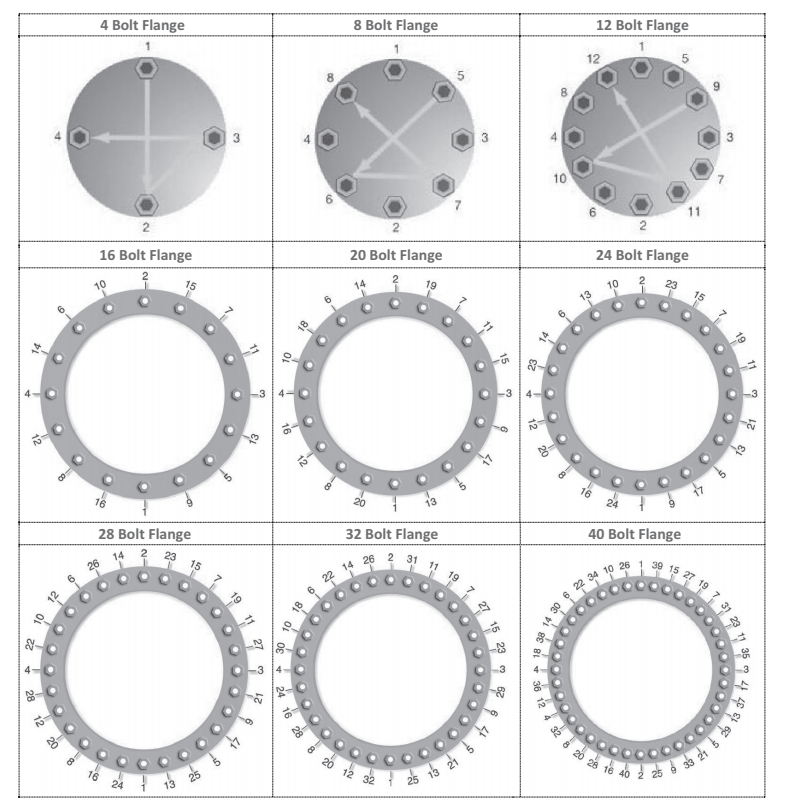
Figure 1: Bolt Tightening Sequence
5.2 Causes of Flange Leakage
- Uneven Bolt Stress: An incorrect bolt-up procedure or limited working space near one side of the flange can result in uneven bolt tightening. This situation may lead to some bolts being left loose, while others crush the gasket.
- Improper Flange Alignment: Flange misalignment, particularly nonparallel faces, can lead to uneven gasket compression, local crushing, and subsequent leakage.
- Improper Gasket Centring: When a gasket is off-center compared to the flange faces, it can result in uneven compression of the gasket, making it more prone to leakage
- Dirty Or Damaged Flange Faces: The presence of dirt, scale, scratches, protrusions, or weld spatter on gasket seating surfaces can create leakage paths or cause uneven gasket compression, leading to potential leakage issues.
- Excessive Loads at Flange Locations: Excessive forces and moments in a piping system at flanges can lead to distortion during operation, potentially causing leaks. Common causes of this issue include inadequate flexibility in the system, the use of excessive force to align flanges during erection, and improper placement of supports, restraints, or expansion loops.
- Thermal Shock: Rapid temperature fluctuations can cause temporary deformation of flanges, leading to leakage.
6. Pressure Testing
After the satisfactory completion of fabrication, the piping is prepared for hydrostatic/pneumatic testing as applicable. The pressure testing follows specific requirements outlined in the engineering specifications for the project and in accordance with applicable codes and standards. The key points related to pressure testing include:
- Shop hydrostatic testing is required for piping spool fabrication, especially when spool painting is completed before installation. This is often specified in isometric drawings or other relevant documents.
- Shop hydrostatic testing is essential before galvanizing of piping spools.
- Pressure piping shall undergo either hydrostatic or pneumatic testing, as specified in the engineering specifications for the project. Usual test pressure for hydrostatic testing is 1.5 times the normal working pressures.
- Testing is conducted in the presence of all stakeholders, and pressure test reports are signed off by all witnessing parties.
- Open-ended vent, drain, and similar piping systems operating at atmospheric pressure are exempt from pressure testing but require leak testing by filling the lines with water.
- Reinforcing pads at branch connections undergo a pad air test at 35 kPa gauge. Weld surfaces are inspected for leaks, and the vent hole is plugged after testing. The vent hole on reinforcing pad shall be plugged with heavy grease or silicon sealant after the test.
- Short pieces of pressure piping removed for the installation of test blinds are tested separately.
- Flanged connections at points where blinds are used during pressure tests do not require separate tests after test blinds are removed.
- Thorough inspection of threaded and socket weld connections is conducted after makeup to ensure tightness.
- Re-testing of any “cut in” or repair work into a line already tested is generally carried out using the same procedure and test pressure as the original test.
- Ensure the insides of all pipes, valves, fittings, and associated equipment are clean and free from loose foreign matter before the pressure test.
- Intervening equipment is normally isolated or removed from the test section. If equipment is included, temporary inline strainers are installed to prevent damage from foreign debris.
- Bench testing of pressure relief valves, calibration, and setting are required before testing
6.1 Test Pack Systems
During the final hydrostatic test of pipelines, it is preferable to test the entire system as a single large piping system. However, there are considerations and exceptions to this approach:
- Design Pressure Differences: When the difference among the design pressures of system components exceeds 15% of the lowest design pressure, testing the entire system as a single unit may not be advisable. The test pressure for the entire connected system should be equal to the test pressure applied to the system component with the lowest design pressure.
If piping systems of different design pressures are fully welded together, cascade pressure testing may be required. This involves completing the pressure test on the higher pressure system before system closure welding and then repeating the full pressure test for the combined systems at the lowest pressure.
- Inclusion of Equipment: Equipment like heat exchangers, pressure vessels, and fired heaters may be included in the test system, provided the system test pressure does not exceed the shop test pressure of any included equipment.
- Excluded Equipment and Components: Certain equipment and components are typically excluded from the piping test pack system:
-
- Rotary equipment (pumps, compressors, turbines)
- Safety valves, rupture discs, flame arresters, and steam traps
- Pressure vessels with sophisticated internals
- Equipment and piping lined with refractory
- Storage tanks
- Filters (if filter elements are not dismantled)
- Heat exchangers with tube sheets and internals designed for differential pressure
- Instruments (control valves, pressure gauges, level gauges, flow meters, excluding thermocouples)
- Excluded Piping Lines: Certain piping lines are often excluded from system hydrostatic testing on-site, including:
-
-
- Package units previously tested by the manufacturer
- Plumbing systems tested according to plumbing codes
- Lines and systems open to the atmosphere (drains, vents, open discharge of relief valves, atmospheric sewers)
- Instrument impulse lines downstream of the first block valve
-
- Testing Medium and Considerations:
- Hydrostatic testing is typically conducted with water, unless freezing or adverse effects on piping material are expected. Approval from the client is required to use other liquids.
- Testing with kerosene or inflammable fluids or compressed air should be avoided if possible, and client approval is necessary if required.
- Pneumatic testing is considered for specific cases, such as gas, steam, or vapor lines where the weight of the hydro test liquid would overstress supporting structures or pipe walls, or when piping with linings is subject to damage by the hydro test liquid.
- Instrument air headers are tested with dry, oil-free air, and commodity test may be used if the instrument air system is completed and operational
6.2 Test Media
When conducting hydrostatic tests on piping systems, the choice of test media is crucial. Specific considerations are made based on the material of the piping system:
- Common Test Media and Filtration:
- The most common test medium is water, and it should be clean for hydrostatic tests.
- Sea water is often prohibited in hydrostatic testing of plant piping.
- Suitable filtration arrangements must be provided at the filling point to prevent the inclusion of foreign matter such as sand and rust in the proposed test water.
- Test Medium for Carbon Steel Piping:
- For hydrostatic testing of carbon steel piping systems, the test medium shall be potable water at ambient temperature. The pH value of the water used for testing should be between 6 and 7.
- Test Medium for Stainless Steel Piping:
- The test medium shall be demineralized water.
- The water should have a chloride content of a maximum of 1 ppm
- The pH of the water should be between 6 and 7.
- Water used for testing should be drained immediately after completion of hydrostatic testing, and the system should be dried out to avoid chloride concentration by dry air blowing.
- Water used for systems with high nickel content should be checked for the possibility of generating hydrogen sulphide (H2S) during the test.
- A water analysis report, including chloride content and pH value, should be attached to the test report for austenitic stainless steel systems.
6.3 Preparation for Testing
- Accessibility of Weld Joints in Test Pack:
- All weld joints (butt and socket) covered by a test pack shall remain accessible during the test.
- Weld joints should not be painted, insulated, backfilled, or covered until the testing is satisfactorily completed as per the approved procedure.
- Surface Preparation and Painting:
- Surface preparation for painting of spools is typically carried out in shops.
- In projects where painting of spools is done after completion of welding, NDT, and PWHT (Post Weld Heat Treatment), hydrostatic testing of spools needs to be completed before surface preparation and painting.
- Another hydrostatic testing may be required after completion of all field welds but before applying coating on field welds.
- Other Hydrostatic Testing Considerations:
- During field hydrostatic testing, all vents shall be open during filling to vent entrapped air before applying test pressure.
- Equipment not subjected to pressure testing should be disconnected or bypassed using temporary piping during the test.
- Safety valves and control valves are not included in site pressure testing.
- Temporary spades and blanks installed for testing purposes should withstand the test pressure without distortion and remain visible during testing.
- Control valves should be removed or replaced with temporary spools or blinded off during pressure testing.
- Check valves should have the flap or piston removed for testing, and locking devices shall be reinstated after the test.
- Spring supports shall be restrained as recommended by the vendor or removed, and expansion bellows shall be removed during hydrostatic testing.
- Drain points for test medium and disposal methodology should follow the pre-approved procedure.
- Overloading of supporting structures should be avoided during hydrostatic testing.
- Piping supported by springs or counterweights should be temporarily blocked up to sustain the weight of the test medium. Holding pins should not be removed from spring supports until testing is completed and the system is drained.
- Pressure in the system should be introduced gradually until it is less than one-half of the test pressure or 170 kPa gauge. Maintain that pressure for 10 minutes. Gradually increase pressure in steps of one-tenth of the test pressure until the specified test pressure is attained
6.4 Test Equipment
- Equipment used in pressure testing includes pumps, safety devices, pressure gauges and recorders, and temperature gauges and recorders.
- Pumps used should be capable of developing the required positive pressure, and measuring devices should have the necessary measuring range.
- All pressure gauges and recorders, as well as temperature gauges and recorders, must be calibrated within 60 days prior to testing.
- Valid calibration certificates should be available on the date of testing.
- Gauges should have a minimum face size of 150mm in diameter and be ranged to approximately twice the test pressure. ASME B 31.3 permits a pressure gauge range from 1.5 to 4 times the test pressure.
- A minimum of two gauges should be provided for each test system.
- One gauge should be located at the highest point, and the other should be positioned soon after the pump or at grade. The latter should be sufficiently away from the pump outlet to avoid damage to the gauge due to pressure jerks from the pump.
6.5 Cleaning
After the test, the piping in the test pack should be drained off completely. Subsequently, the line may need to be flushed to remove all foreign matter. Flushing can be done using clean water, preferably from the hydrostatic test, as long as it does not get contaminated.
During flushing, it is recommended not to flush inline instruments.
Additional cleaning may be required for specific applications like compressor and turbine inlets, lube oil piping, etc. A separate cleaning procedure should be approved by all concerned before starting hydrostatic testing.
It is advisable to dry the piping and all connected equipment to a reasonable level and maintain this condition until commissioning, especially in humid areas where the time gap between hydrostatic testing and commissioning is considerable
Knowledge Hub

