
Novelty Steel Supplies Piping Components such ss Pipes, Pipe Ends, Piping Fittings, Valves, Bolts, Gaskets and Piping Supports.
To interconnect various process and utility equipment within a process plant, a combination of piping components is utilized, collectively referred to as a piping system. Each component possesses distinct characteristics, both advantageous and disadvantageous, and it is crucial to understand their strengths and weaknesses.
1. Introduction
A piping system is comprised of various components with each has different function and characteristics. The essential components required to construct a piping system includes the following elements.
2. Pipe
The pipe serves as the primary connection between various pieces of equipment in a process plant, acting as the main artery of the piping system. Despite being the seemingly simplest component, it possesses unique features.
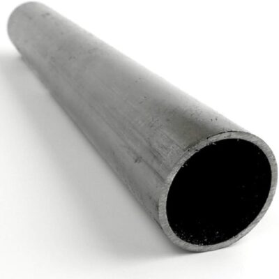
Photo 1: Steel Pipe
- Pipe Material Composition:
- In ASME B31 code-designed plants, metallic pipes are typical.
- Metallic materials include carbon steel, stainless steel, duplex, copper
- Nonmetallic pipes like PVC, glass-reinforced epoxy, or glass-reinforced plastic are allowed, each with unique characteristics.
- Identification and Wall Thickness:
- Identified by nominal pipe size (NPS) in U.S. customary units or diameter nominal (DN) in metric units.
- Wall thickness specified in terms like Standard weight (STD), extra strong (XS), or double extra schedule (XXS).
- Carbon and stainless steel pipes have specific schedules with different wall thicknesses.
- Steel Pipe Production Methods:
- Produced through seamless, longitudinally welded, or spirally welded methods.
- Seamless and longitudinally welded pipes are most common.
- Seamless pipes available up to 24 inches; longitudinally welded pipes specified for sizes above 16 inches, but can be made in smaller sizes.
- Seamless Pipe Formation:
- Formed by passing a solid billet through a metal bar at elevated temperature.
- Sizing rollers shape the outside diameter (O.D.), and billet size determines inside diameter (I.D.).
- Seamless pipes have a quality factor (E) of 1.0.
- Longitudinally Welded Pipe Formation:
- Created by rolling hot steel plates into a circular section.
- Edges of the pipe are squeezed together and welded.
- Initially, longitudinally welded pipes have a quality factor (E) of 0.85.
3. Pipe Ends
Pipe ends can be supplied in several variations; these are the most commonly specified within ASME B31.
- Plain End Pipe:
- A cut at a 90° angle perpendicular to the outside diameter.
- Can be re-prepared for threaded or butt-weld ends.
- No standard for plain end due to its simple geometry.
- Threaded Ends:
- Specific geometry depending on wall thickness, specified in ASME B1.20.1.
- Requires a coupling with matching threads to connect to lengths of straight pipe.
- Full coupling dimensional design covered by ASME B16.11.
- Internal threads governed by ASME B1.20.1, covering dimensions and gauging for general purpose applications.
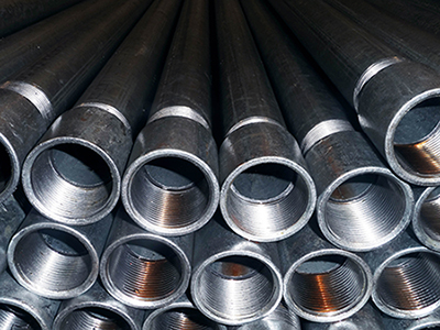
Photo 2: Threaded Pipe Ends
4. Piping fittings
Components for pipe fittings enhance the functionality of straight pipes, and it is essential for both to exhibit compatibility in terms of both chemical and mechanical aspects within a piping system. These fitting components serve various purposes within the system.
- Change of direction-90″ and 45″elbows.
- Change of direction-equal tee
- Reduction in pipe size
- Reduction in pipe size and change of direction-reducing tee
- Pipe joint-flange, coupling, union.
- Mechanical joints-flanges
For projects adhering to the ASME B31 code, pipe fittings are manufactured according to standardized dimensions determined by their size and wall thickness. These consistent dimensions play a crucial role in enabling a piping designer to efficiently plan and lay out the piping system.

Photo 3: Pipe Fittings
Various welding methods can be employed to connect these piping components. These methods include butt-welding, socket welding, or using threaded ends. Additionally, connections can be established through flanges involving bolts and gaskets, or through proprietary mechanical joints such as those provided by Victaulic and hub ends.
5. Valves
In a piping system, valves stand out as the most intricate components. Unlike pipes and fittings, valves are comprised of multiple components, featuring a diverse range of materials and both static (stationary) and dynamic (moving) parts. Serving as a crucial element within a piping system, valves, depending on their design, possess the capability to transport liquids, gases, vapours, and slurries.
In addition, valves play a vital role in the control of process flow, performing functions such as starting, stopping, regulating, and checking. Their significance, both commercially and functionally, is often underestimated in a process plant. The commonly utilized valves in projects adhering to the ASME B31 code include;
- gate valves
- globe valves
- check valves
- ball valves
- plug valves
- butterfly valves
- pinch or diaphragm valves
- control valves
- Pressure relief valves.
Each of these can be further categorized based on their design and materials of construction.
Valves can be operated manually by personnel or through an independent power source, be it electric, pneumatic, or hydraulic, depending on the power requirements and availability. A valve, being a multicomponent item, incorporates both dynamic and static parts and can be constructed from metallic or non-metallic materials. Valves perform various functions, such as;
- starting/stopping flow (e.g., butterfly valve as an isolating valve like gate, ball, or plug valve)
- regulating flow (e.g., butterfly valve as a throttle or globe valve)
- preventing backflow (non-return or check valve), and controlling flow (control valve)
Valves selected for ASME B31 code projects are subject to numerous international standards and specifications. These standards cover the type of valve, design, construction, components, dimensions, testing, and marking.
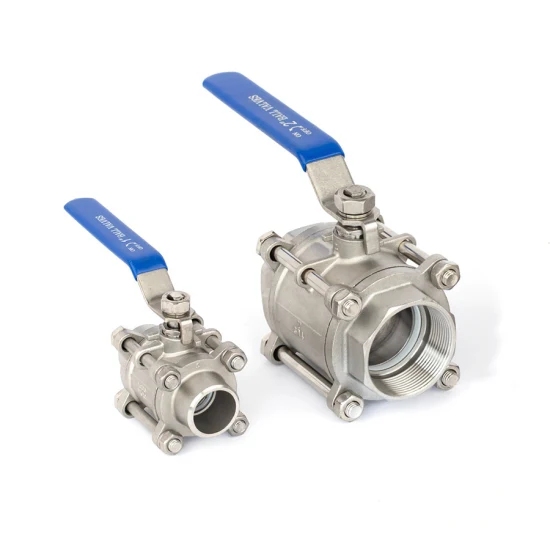
Photo 4 : Pipe Valves
6. Bolts and gaskets (fasteners and sealing)
It is advisable to steer clear of potential leak paths in a piping system whenever possible. However, there are instances when their presence becomes necessary for construction and maintenance purposes. Achieving a leak-free joint is feasible when proper materials are selected, the bolting method is appropriate, the necessary procedures for creating a leak-free joint are followed, and qualified personnel are available.
The bolted flanged joint represents a potential vulnerability in a piping system, and it is crucial to strictly adhere to the design limitations of the flange type and the materials of construction to prevent any malfunction or leakage. While a flanged connection offers the advantage of easier assembly and disassembly compared to a welded joint, this benefit is contingent on the mechanical joint being leak-free.
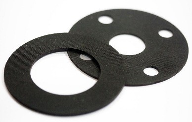
Photo 5: Pipe Gaskets
To ensure a satisfactory joint, various international standards address the individual components essential for a bolted joint, including flanges, gaskets, and bolts. Strict adherence to these standards is necessary for designers to create bolted joints that guarantee mechanical integrity.
Attaining a leak-free mechanical joint involving a flange face, gasket, and bolting is feasible when careful consideration is given to the following areas and relevant international standards:
- Pressure and temperature design conditions of the internal fluid: Ensure that the joint is designed to withstand the pressure and temperature conditions of the internal fluid as specified in relevant standards.
- External environmental conditions: Consider the external environment to which the joint will be exposed and choose materials and methods that can withstand these conditions.
- Flange face design: Adhere to appropriate standards for flange face design to ensure compatibility and proper sealing.
- Flange material: Select flange materials in accordance with international standards, taking into account the specific requirements of the application.
- Gasket type and materials of construction: Choose the appropriate gasket type and materials based on the fluid, temperature, and pressure conditions. Follow relevant standards for gasket selection.
- Fastener (bolt and nut) material: Comply with standards specifying the material requirements for bolts and nuts to ensure they meet the necessary strength and corrosion resistance criteria.
- Bolting lubricant: Use an appropriate bolting lubricant that is compatible with the materials used and meets industry standards.
- Bolting procedure – torque tensioning and bolt-up sequence: Follow standardized procedures for torque tensioning and the bolt-up sequence to achieve proper tightening and prevent leaks.
- Skilled workforce: Ensure that the personnel involved in assembling the joint are qualified and skilled in the procedures outlined by international standards.
By addressing these aspects and adhering to relevant international standards, the likelihood of achieving a leak-free mechanical joint is significantly increased. This will promote the integrity and reliability of the piping system.
7. Piping Supports
The accurate and cost-effective selection of supports for a piping system often poses challenges of varying degrees, ranging from minor to critical. It is crucial to make proper support selection a primary objective throughout the design and construction phases.
Photo 6: Pipe Supports
To minimize or prevent pipe support problems, particular attention should be given to support considerations during the piping layout design phase. The piping designer’s familiarity with support issues, established practices, and commercially available pipe support components and their applications holds significant importance.
Effective pipe support design starts with well-thought-out piping design and layout. Utilizing the surrounding structure for logical and convenient support, anchorage, guidance, or restraint points is recommended. Piping should be routed to allow ample space at these points for the use of appropriate components. In the case of parallel lines, both vertical and horizontal, sufficient spacing should be maintained to accommodate independent pipe attachments for each line.
Project-specific pipe support specifications must be formulated to ensure proper support under all operational and environmental conditions, accounting for slope, expansion, anchorage, and insulation protection. A strong understanding of standard practices, industry customs, various types and functions of commercially available component standard supports, and awareness of their advantages and limitations can greatly contribute to achieving the desired results.
The financial investment in the support system is typically overshadowed by the considerably higher value of the pipes, valves, and fittings that require support. Neglecting to allocate adequate time for the design, procurement, and fabrication of supports can result in expensive delays during erection and necessitate the use of temporary supports.
8. Conclusion
These components, whether pressure-containing or non-pressure-containing, come together to constitute the elements of a piping system. Despite differences in commercial value and availability among individual components, each holds equal importance in ensuring the safe and efficient functioning of the piping system.

