
Pressure Vessel Manufacturing For Energy, Oil and Gas, Mining, Water Treatment, and Industrial Project Takes Place in Our Facilities in Turkey.
The manufacturing of pressure vessels begins with rigorous inspection of raw materials, following with forming, welding and NDT processes to achieve the desired integrity and safety of the finished pressure vessel according to the codes.
Index
2.4 Set-Up for Welding of Long Seams and Inspection
2.5 Precautions to Control Distortion
3.5 Stiffeners to Maintain Circularity
4. Non Destructive Testing (NDT)
5. What is Novelty Steel Offering?
1. Raw Material Inspection
- Raw materials for pressure vessel manufacturing are ordered from reputable vendors with proper certification.
- Upon receipt, the Quality Assurance and Control (QAC) department is notified through an intimation note.
- Relevant documents are forwarded to QAC by the procurement department, with a copy sent to the planning department.
- Raw materials are stored in the incoming material inspection bay, except for plates and pipes stored separately in the open yard.
- Inspection results are indicated by green (accepted), yellow (on hold), or red (rejected) stickers with initials and date.
- Items under hold trigger clarifications from other departments, and discrepancies are detailed in an inspection note.
- Accepted materials receive a green sticker, while those not meeting PO or code requirements are labelled with a red sticker.
- Rejected items are communicated to the vendor by the procurement department, and alternative procurement is initiated.
1.1 Dished Ends
- Each dish is identified against its certificate
- Physical verification includes measuring outside circumference, inside diameter, thickness at straight flange, and inside depth.
- Heat number and identifications certified by the third-party inspector are cross-checked.
- The certificate is verified for material specification, types of tests, heat treatment, etc.
1.2 Plates/Piping
- Measure physical dimensions, especially thickness.
- Correlate item identification with the certificate.
- Verify the certificate against code and PO requirements.
- Acceptance if all parameters align.
1.3 Pipe Fittings
- Record dimensions and verify against applicable standards.
- Cross-check item identification with the certificate.
- Verify the certificate against PO and code requirements.
1.4 Fasteners and Gaskets:
- Conduct a dimensional check on random samples.
- Correlate certificates to the lot identification.
- Check certificates for compliance with PO and code requirements.
1.5 Ready-Made Cans:
- Identify the shell and measure outside circumference, length, and thickness.
- Cross-check with certificate dimensions.
- Verify compliance and acceptability for non-destructive testing from the certificate.
1.6 Cones:
- Identify the cone through stamping details on plates.
- Check measurements against given dimensions.
- Verify the certificate for compliance with PO and code requirements.
2. Plate Forming
2.1 Direction of Bending:
- The shell plate’s strength is higher in the direction of rolling.
- Bending should align with the original direction of rolling
2.2 Pre-pinging:
- In the bending machine, both ends of the shell plate are first pressed into the required shape (pre-pinging).
- Profile at the ends is checked using a template; full bending follows.
- Bending is done in stages to minimize elongation, eliminating the need for further trimming.
2.3 Templates:
- Templates for profile checks during bending follow UG 29.2 requirements, twice the arc length from chart UG 29.2.
- A segmental template with a 20° subtended angle meets ASME requirements.
- The QA/QC engineer verifies the profile and chord length, stamped with the inspection engineer’s mark.
2.4 Set-Up for Welding of Long Seams and Inspection:
- After bending, the longitudinal seam is fitted for welding, with dimensions recorded
- Profile checks ensure adherence to the template; deviations beyond acceptable levels are repaired.
- V configuration compliance with design, uniformity, and preset/restraint adequacy are verified.
2.5 Precautions to Control Distortion:
- Distortion prevention measures for long seams include peaking in or out.
- Single-V double-welded joints for plate thickness <16mm, groove inside.
- Double-V joints for plate thickness >16mm, unequal V with major V inside.
- During inside welding, two spiders are positioned at both ends, avoiding the weld area for easy access.
- Before back-gouging, two more stiffeners are added, maintaining preset up to D +5mm based on the shell diameter.
- Additional channel stiffener over the weld seam may be removed before radiographic testing (RT); three remaining spiders retained until the vessel takes its final shape.
3. Welding
3.1 General Considerations
-
- Welding should be carried out by qualified welders following approved procedures.
- Acknowledge that every weld has the potential for distortion.
- Distortion can be minimized with careful precautions.
- Distortion control is vital in pressure vessel manufacture, but often overlooked in related literature.
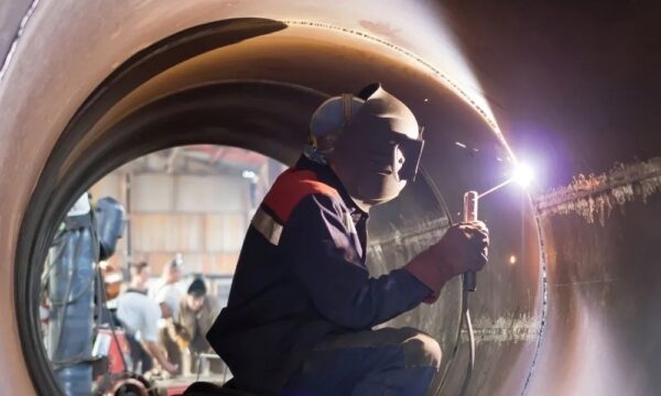
Photo 1 : Pressure Vessel Welding
3.2 Edge Preparation
-
- Proper edge preparation significantly controls distortion.
- Rational design minimizes the amount of weld metal used, reducing distortion.
- For shells up to approximately 16mm thickness, single-V double-welded butt joints are recommended. For thicker shells, double-V double-welded butt joints are preferred.
- Specific guidelines for applying V sizes and angles are needed to reduce distortion.
3.3 Tack Welding of Joints
-
- Use tack welding, clamps, and wedges for joint alignment.
- Qualified welders should perform tack welding using approved procedures, including preheat conditions.
- Properly prepare tack welding stopping and starting points by grinding.
- Maintain tack spacing of 200 to 250 mm with tack lengths ranging from 25 to 40 mm.
- Retain holding devices until welding from the major V side is completed to manage distortion.
3.4 Run-In and Run-Out Plates
-
- Provide plates at the beginning and end of each seam, preferably with the same V configuration.
- This practice helps welders start from the run-in plate, stabilizing welding by the time they reach the shell, ensuring defect-free welding.
3.5 Stiffeners to Maintain Circularity
-
- Use angle iron spiders, with adjustment provision, to maintain circularity while rotating shells on the floor and rotators.
- Provide at least four spiders at both ends of the shell, avoiding the longitudinal seam area.
- Include one additional stiffener on the weld with a preset to counteract shrinkage forces, ensuring an acceptable weld seam profile.
3.6 Pre-cleaning of Welds
-
- Prior to welding, meticulously clean the weld seam and the area on either side of the V groove (at least 25 mm wide) from rust, grease, mill scale, or any foreign material.
- Use a circular wire brush attached to a grinding machine for effective cleaning, as simple wire brush cleaning may be insufficient.
3.7 Preheating
-
- Depending on the shell section material and WPS, preheating may be necessary before welding.
- Use appropriate attachments to achieve the required preheat temperature.
- Measure the temperature using temperature chalks.
3.8 Sequential Welding
-
- For longitudinal seams, ensure controlled gap sizes at the starting and closing ends.
- For seams longer than 2 m, consider staggered welding.
- Begin welding from one end to a specific length, then start from the other end and complete the remaining portion.
3.9 Balancing of Welds
-
- During back-gouging, aim for an equal V joint from both sides.
- Avoid exceeding half the shell’s thickness with an unequal V joint from the minor V side.
- Ensure V width does not exceed design specifications while maintaining a V angle of at least 10 to 15 degrees.
3.10 Final Visual Examination
-
- After completing welds on either side, remove restraints.
- Retain spiders, especially for thin shells, until the vessel is complete.
- Inspect weld joints from both sides using an inside or outside template.
- Assess peaking, surface finish, reinforcement, profile, undercuts, spatters, and removal of tack metals.
- Release welds for non-destructive testing (NDT) if all inspection parameters meet code or client specifications.
4. Non Destructive Testing (NDT)
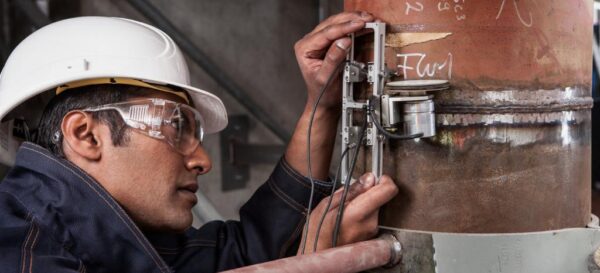
Photo 2: Pressure Vessel Quality Control
4.1 NDT Methods
-
- After a satisfactory visual inspection, pressure vessel seams are subjected to NDT.
- The primary method is Radiographic Testing (RT), but Ultrasonic Examination (UT) may be substituted for final closure seams if interpretability of radiographs is challenging due to vessel construction.
- Ultrasonic examination follows the technique and acceptance criteria in accordance with Appendix 12 of ASME Section VIII Div. (1).
- Other welding tests include Magnetic Particle Testing (MPT) and Liquid Penetrant Testing (LPT).
4.2 Radiographic Testing (RT)
-
- The requirement for RT can be either full or spot depending on the joint efficiency considered in the design.
- Full Radiographic Testing:
- Specified in UW 11 and UW 51.
- Required when the joint efficiency is considered as one in design.
- Mandatory for butt welds in shells and heads of vessels carrying lethal substances.
- Also required for butt welds in shells with thickness exceeding 38.1mm.
- Spot Radiographic Testing:
- Governed by TPW 52.
- The designer decides whether to use spot RT based on the assumed weld efficiency factor.
- According to the code, one spot on each vessel is required for each 50-ft (15.2-m) increment of weld or fraction thereof.
- The minimum spot size should be 6 in. (150 mm).
- If an initial spot RT film does not meet acceptance criteria (UW 51), two additional spots away from the initial spot are taken.
- If these two additional spots are acceptable, and the original spot is repaired with a new radiograph that meets acceptability standards, the joint represented by these welds is considered accepted.
- If either of the additional spots fails to meet requirements, the entire length of the weld represented by that spot must undergo full radiography.
- Acceptance standards for linear defects are per UW 51, while rounded indications follow the criteria outlined in Appendix 4.
These NDT methods ensure the integrity of pressure vessel welds, allowing for the safe and reliable operation of the vessel. The choice between full and spot radiographic testing depends on design considerations and weld efficiency factors.
5. What is Novelty Steel Offering?
Novelty Steel offers pressure vessel fabrication complying with ASME Codes.


