
Novelty Structures designs and fabricates industrial ducts for various projects.
The below guide highlights the importance of thorough planning in shop and field fabrication, shipping, and erection for efficient design and implementation.
1. General Considerations for Ducting
Certainly, the planning of shop and field fabrication, shipping, and erection is crucial when designing a ductwork system. Before initiating the structural analysis and design, thorough consideration of these practical aspects is essential. A truly optimized ductwork design incorporates efficient strategies for fabrication, transportation, and installation. This holistic approach ensures that the design not only meets structural requirements but also facilitates seamless implementation.
1.1 Shipping Modes and Dimension Considerations
Shipping costs play a crucial role in ductwork projects, influenced by factors such as project location, shipping distance, and component size. Modularizing ductwork in a fabrication shop rather than fieldwork can lead to cost savings and enhanced quality. The ductwork structural engineer must be aware of the chosen shipping method, and the design should align with it. The three primary shipping modes are rail, truck, and ship, with trucking being the most common. Piece width is often a critical factor in truck shipping costs, with height and length also being considerations. Weight, while important, is usually not the primary controlling factor. Specialized requirements for ship and rail shipping should be thoroughly investigated based on project needs.
- Field Construction Costs: Field construction costs are crucial but challenging to obtain during the design stage, particularly data related to site-specific costs and crane capacity. Lack of information may be due to the absence of an erection contractor during the initial design phase.
- Site Specific Requirements: When available, comprehensive data on field construction costs should be considered in the design process, including crane capacity and site-specific requirements.
- Shop Fabrication: Historically, engineers understand that shop fabrication is generally less expensive than field construction. Operations like welding, cutting, fitting, and handling are of higher quality when performed in a fabrication shop.
- Preference for Shop Work: Given the cost advantage and higher quality of operations, it is advisable to specify as much shop work as possible in the design, emphasizing the importance of fabrication shop processes over on-site construction.
- Partial Preassembly: When feasible, ducts with suitable dimensions can undergo partial preassembly into box sections or smaller C-shaped modules in the fabrication shop.
- Stiffened Panel Preassembly: Conventionally constructed stiffened panels can be preassembled in the fabrication shop to form ductwork sections of varying lengths.
- Cost Considerations: While shop preassembly involves higher shop labour and shipping costs due to larger pieces, it results in reduced field labour expenses, which are typically more expensive and of lower quality.
- Insulation and Lagging: To minimize field labour further, insulation and lagging can be installed in the shop before shipping the preassembled sections to the field.
- Benefits of Preassembly: Extensive shop preassembly can reduce critical construction time, improve worker safety by minimizing work above grade, and potentially shorten the overall project schedule.
- One-Piece Shop Construction: When duct size allows for one-piece shop construction of rectangular and circular ducts, the choice between box construction and panel construction depends on factors like labour costs, shipping costs, and project schedule considerations.
- Engineering Responsibility: Clear engineering responsibilities for preassembled pieces should be defined at the project’s outset, and considerations for loads during lifting, shipping, and erection must be addressed by either the rigging engineer or the structural engineer when modularizing sections of ductwork.
1.3 Field Splices
Field splices, or joints, are common in ductwork, occurring at corners and panel-to-panel joints for rectangular ducts, and where lengths are joined for circular ducts. Various configurations are used based on project needs and fabrication techniques. Collaboration between the structural engineer, fabricator, and erector is crucial in selecting the right configuration. Wide-flange profiles, E bolts, and seal welding practices are utilized for effective field splicing. The chosen configurations vary for different duct sections and sizes, considering factors like adjustability, strength, and ease of fit-up. It is recommended to avoid lap-type joint configurations for box sections and circular sections, opting for butt-type or flange-type splices for better adjustability during erection.
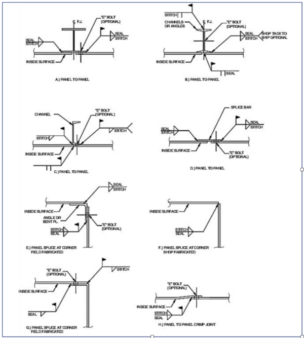
Figure 1: Field Splices for Ductwork
2. Ductwork Fabrication
The Ductwork designer plays a significant role in ensuring the quality of the erected product. One key responsibility involves specifying fabrication requirements and acceptable tolerances for both fabrication and erection. By doing so, the structural engineer contributes to achieving a high-quality installation of ductwork. This proactive approach helps establish clear guidelines and standards for the fabrication process, ensuring that the final product meets the required quality standards.
2.1 Plate Fit-Up
- Ensuring Duct Plate Squareness:
- Design engineer plays a crucial role in achieving duct plate squareness by considering plate fit-up during the arrangement phase.
- Plate fit-up involves recognizing final dimensions, required gap spacing for welding, and acceptable tolerances.
- Temporary Bracing for Tolerances:
- Temporary internal and external braces are essential to maintain fabrication and erection within acceptable tolerances.
- Depending on duct size, the structural engineer should contribute to designing temporary bracing.
- Fabrication Process Considerations:
- Proper splice preparation for welding and bolting is critical in the fabrication process.
- Elements like edge bevelling, backing bar attachment, and match drilling require careful attention.
- Tolerance Management:
- Tolerances should not be accumulated unless the design explicitly considers it.
- Special care must be taken during the fabrication process to prevent tolerance-related issues.
- Typical tolerances :
- The misalignment between plates in any butt joint should not surpass 33% of the thickness of the thinner plate. In the case of clad plates, the maximum allowable misalignment is 1 mm.
- The out-of-squareness of the rectangular duct cross-section should not exceed 1% of the diagonal measurement or 13 mm, whichever is smaller.
- For circular ducts, the out-of-roundness of the cross-section should not exceed 1% of the internal diameter. However, the plate mismatch between adjoining pieces should not go beyond 33% of the thickness of the thinner plate.
- Peaking of circular duct seams, measured by an 0.5 m long template centred at the weld seam and cut to the prescribed radius, should not exceed 6 mm from a true circle.
2.2 Welding
In ductwork construction, welding is a crucial operation, and the quality of the completed ductwork is often evaluated based on the quality of the welding involved.
- Advancements in Welding Processes: Over the years, welding processes and methods have improved significantly, with widespread adoption of automated processes for enhanced quality and productivity.
- Consulting with Welding Experts: Consulting with welding or metallurgy specialists is crucial to prevent expensive repairs and ensure the delivery of high-quality ductwork. A foundational understanding of welding is necessary for effective collaboration in ductwork construction between duct designer and welding specialists. Duct designers need to consider accessible welded joints that are both structurally adequate and economical to construct, preventing limitations in access and ensuring efficient welds.
2.3 Shop Inspection
Regular shop inspections are essential during the fabrication process and should involve the customer and structural engineer. The inspection schedule must be agreed upon at the project’s outset and consistently adhered to. The fabricator should conduct daily inspections as part of an ongoing effort, with some adopting total quality management practices. The inspection should cover the following minimum items:
- Weld Quality: Adherence to specified welding requirements (AWS, ASME, or others) is crucial. Standardized inspection procedures for weld quality, as per the specified welding methods and procedures, must be followed. The fabrication specifications or ductwork drawings should indicate any additional welding test beyond the minimum requirements in the applicable welding specification.
- Dimensions: Verification of dimensions is essential. Tolerances specified in design drawings, the fabrication contract, and relevant codes such as AWS or ASME should be strictly followed.
- Material: Review of material purchase orders and mill material test reports is necessary to ensure compliance with project specifications.
- Fabricator’s Records: The fabricator should maintain inspection records, which should be readily available for review.
2.4 Surface Preparation
As most ducts are crafted from some form of carbon steel, it is often advisable to apply surface protection after fabrication, regardless of the final specified surface treatment. The choice of surface protection depends on the specific surface and the intended final coating applied in the field.
- External Surfaces:
It is recommended to perform degreasing, remove weld splatter, and clear fabrication debris as the minimum surface preparation. Applying a subsequent coat of primer paint is recommended to prevent surface corrosion during shipping and storage. In some instances, it may be desirable to apply an additional coating. Certain components such as instrument port flanges should be greased, coated, covered, or otherwise protected before leaving the fabricator’s shop.
- Internal Surfaces:
In addition to the steps outlined for external surfaces, special treatment for internal duct surfaces may be specified for heat or corrosion protection. Supports for linings are often applied in the shop. Care must be taken by the fabricator to protect internal surfaces and shop surface preparation from potential damage or contamination during transit.
- Stainless Steel:
For external and internal surfaces of stainless steel and high-nickel-alloy ducts, passivation (acid wash followed by neutralizing) is recommended in the shop before shipment to clean the surfaces of iron contamination. Procedures should be implemented in the fabrication shop to eliminate cross-contamination of dissimilar metals.
3. Handling & Shipping
3.1 Marking
Each piece, assembly, and subassembly shipped independently by the fabricator must be clearly marked with a unique erection and shipping mark number. The same mark numbers must also be prominently displayed on the erection drawings.
Mark numbers should be applied to components using durable, high-visibility paint in a conspicuous location. The size of the mark should facilitate easy readability. Ideally, each individual piece should bear at least two identical marks on opposite surfaces.
3.2 Lifting Lugs
The handling of large ductwork components or assembled sections typically requires lifting devices, especially when shipped preassembled. Lifting lugs are essential in facilitating this process, and collaboration between the ductwork engineer, fabricator, and erector is crucial to determine their requirements. Design drawings may suggest lifting lug locations, but input from those handling the lifting is necessary to avoid misplacement. Precautions for inappropriate handling should be clearly outlined in the design drawings and fabrication specifications.
A construction impact factor of 1.5 is considered during design, and the contractor or a qualified rigging engineer may design lifting lugs and attachments. The rigging engineer prepares design calculations and drawings for the lifting lugs, which are then reviewed by the structural engineer.
Sizing lifting lugs involves determining lug material and the design load, with a 50% increase to account for lifting impact effects.
3.3 Temporary Bracing
The fabricator responsible for shipping ductwork components is also accountable for providing any necessary temporary bracing during transportation to ensure components arrive undamaged and within tolerance. This bracing is crucial for stability during shipment and erecting at the project site.
The designer may assist the erector in determining bracing needs, and ASCE 37 provides guidance on types, magnitude, and duration of loads for evaluating structures during erection. Circular ducts, due to their susceptibility to plate buckling during transportation, require special consideration. Analysing and designing them for impact during shipping should include provisions for duct supports, bracing elements, and the plate itself.
Temporary bracing marked by the fabricator should clearly indicate its non-permanent nature, typically through paint coding. Occasionally, the structural engineer may note temporary bracing requirements on design drawings, particularly for large pieces or those with critical dimensional tolerances.
Novelty Structures has been fabricating industrial ducts for various projects.


